
Evaluating the Structural Performance of Unreinforced Monumental Masonry Structures
Even when they are intact, monumental historic masonry structures – including structural systems such as towers, domes, arches, tunnels, buttresses, and vaults – are complex structural systems whose behavior is difficult to quantify using only simple analytical methods. Some of the parameters that complicate the analysis approach are the indeterminate behavior of large interconnected systems, intractable boundary conditions, the variability of materials, direction-dependent strength properties of masonry, and deterioration. When cracks occur, structural behavior changes as displacements take place, and loads are redistributed throughout the structure.
Frequently, conditions such as moisture intrusion or cracking, movement, and deterioration of mortar, brick, stone, or terra cotta prompt an evaluation of the structure to understand the causes, as well as the implications that include diminution in structural integrity and prognosis for future performance. This often prompts structural engineers to opine on whether a deteriorated masonry structure is safe.
The solution to this problem often requires structural engineers to engage in rigorous investigations to reveal the construction and condition of a structure, and then to combine classical analysis techniques that explore the design intent with sophisticated modern tools to assess performance with distress. When properly executed, finite element computer programs, which engineers commonly apply to analyses of structures with known configurations and properties, can model the behavior of complex masonry structures with uncertain properties. The model must be carefully developed to strike a balance between model complexity, level of confidence in the structure being modeled, and the need to achieve meaningful results. Although modeling results can be informative, they should be considered one constituent of a carefully planned engineering study to evaluate a historic structure’s condition and performance.

Figure 1: Pennsylvania State Capitol Building.
The Pennsylvania State Capitol Building (Figure 1) in Harrisburg, Pennsylvania, constructed circa 1906, is an example of a monumental masonry structure assessed using finite element techniques. The Capitol structure has complicated geometries with an upper drum and colonnaded peristyle, lower drum, and four supporting vaulted arches with intersecting pendentives (Figures 2 and 3). This unreinforced load-bearing masonry construction supports a truss framed dome, a colonnaded lantern, and a statue above. The lower drum contains a circumferential arched tunnel below the peristyle deck.
Figure 2: Central dome structure. Detail from drawing A-6: Restoration of the Peristyle Deck by Perfido Weiskopf Wagstaff & Goettel dated 2008 with annotations by SGH.
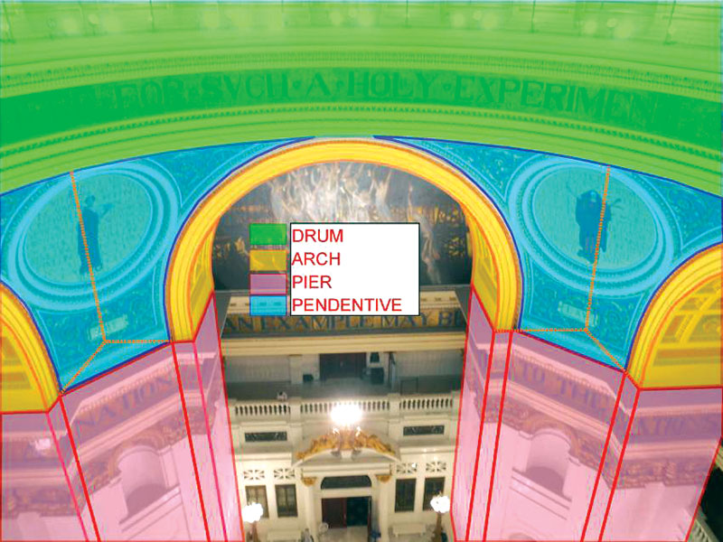
Figure 3: Computer enhanced image identifying components of central dome structure.
During work associated with restoration of the peristyle deck (Figure 4) to address leakage below the dome structure, the restoration team noted cracking and moisture-related deterioration of the brick and granite masonry drum below the deck. The State of Pennsylvania’s Office of General Services, concerned about this distress, commissioned an engineering study to evaluate the structural performance of the brick masonry of the lower drum, including consideration of the observed masonry deterioration and cracks.
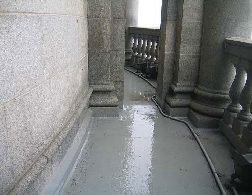
Figure 4: Peristyle deck above the lower drum.
Configuration
Part of the challenge in analyzing monumental unreinforced masonry structures is understanding and adequately modeling the structural configuration and the materials of construction. Engineers often are hampered by the lack of drawings, and by access to assess materials and construction deep inside thick structural elements.
Thick masonry construction often contains a combination of exterior stone and interior brick. There may be voids inside massive construction that appears solid from the outside. When reliable drawings are not available, the engineer must use prudent investigation and judgment to identify critical features of the structural system. In the case of the Capitol assessment, exploratory openings, drilled cores, and masonry removals for ongoing waterproofing repairs revealed that the typical wall construction consists of regularly coursed interior brick, making up the greatest portion of the wall thicknesses, and exterior granite ashlar. Stone and brick are interconnected with stone header courses that primarily occur at counterbalanced stone cornices that extend into the brick masonry backup. In their archives, the State maintains original building drawings that provide additional information about the thick masonry construction, not revealed by limited openings and removals (Figure 5).
Figure 5: Tunnel Section. Detail from drawing A79: Elevation inside of dome from balcony steel trusses by Huston dated 1903. Courtesy of Joseph M. Huston.
Materials
Masonry, the material, is strong in compression and weak in tension. Shear strength often is a function of the level of compression and the direction of force application. Therefore, unreinforced masonry structures primarily achieve their strength through a combination of compression and shear resistance, and structural mass and configuration usually determine the magnitude of compression. However, masonry structures rarely are constructed to completely avoid tensile stresses, so tensile strength – low though it often is – usually plays a role in load resistance. Hence, understanding both compressive and tensile strengths of masonry is important for understanding structural performance, and potentially the overall stability.
Strength and stiffness of masonry construction varies greatly depending on the materials (e.g., stone, brick, and mortar materials). The strength of a single material (e.g., brick) can also vary within a structure. For instance, strong, durable, well-fired bricks are typically placed in exterior exposed conditions and softer lesser quality bricks are placed at the protected interior. The stiffness and strength of different stone types varies widely; even a single stone type such as granite can vary in material properties depending on its composition and origin.
Tensile strength of historic masonry depends primarily on mortar properties and its constituents (cement, lime, and sand). The tensile strength of mortar often is assumed to be low, and generally should be considered zero for soft mortars.
In an effort to thoroughly assess the Capitol, the study team extracted brick masonry prisms for laboratory flexural and compressive strength testing to determine tensile strength, compressive strength, and stiffness properties.
Varying and Changing Conditions
Masonry deteriorates over time, impacting the overall strength and performance of the structure. This deterioration usually impacts stress levels in masonry structures and, in some cases, can impact load paths. The type and extent of deterioration of masonry/mortar can vary throughout a single structure and is dependent on a variety of factors, including quality of materials, initial construction quality, location, exposure, and maintenance program.
Cracks in brick masonry result from tensile stresses and/or shear stresses. Sources of these stresses include, but are not limited to, restraint of volume change, lateral thrusts from structural configurations, superimposed loads, and differential building settlement. Volume change can be driven by irreversible expansion (i.e., brick growth) and cyclical expansion and contraction due to seasonal and daily temperature and moisture fluctuations.
The location, orientation, and extent of cracked or deteriorated masonry must be understood to evaluate whether the structural performance of the component and overall gravity and lateral-load-resisting systems are negatively impacted. The progression of masonry deterioration over time can lead to load redistributions, which can contribute to additional cracking and distress and further load redistribution. Masonry walls may lean, and arches/domes may flatten from lateral thrust, yet still maintain overall stability. The assessment of the extent of impact caused by deterioration and cracks requires structural evaluation with careful consideration of geometry, material properties, structural conditions, and analysis approaches.
Conditions in the Capitol
The Capitol did not have readily visible signs of global displacements, but had localized downward displacement and cracking of granite peristyle pavers below colonnades.
Figure 6: Crack survey in tunnel of lower drum.
The arch of the circumferential tunnel had a continuous crack at its crown and transverse cracks below the colonnades (Figure 6). Longitudinal cracks near the intersection of the exterior wall and tunnel floor were also observed. The systemic nature of longitudinal cracks appeared to relate to the outward thrust of the tunnel arch. The repetitive nature of the transverse cracks appeared more likely caused by the intrinsic stress pattern derived from the complicated, indeterminate configuration of the dome structure – perhaps a combination of flexural stresses from superimposed colonnades and hoop stresses. No cracks were found that were consistent with cracking due to differential settlement.
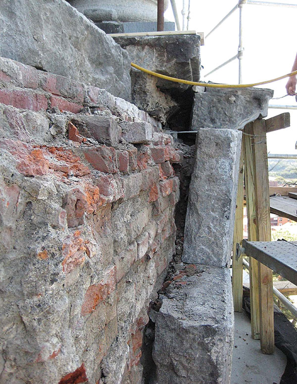
Figure 7: Deteriorated masonry behind granite ashlar cladding at exterior of lower drum.
The Capitol structure had washed out mortar and deteriorated brick masonry behind granite ashlar cladding (Figure 7). Some delaminated masonry in the circumferential tunnel was associated with corrosion of embedded metal pipes.
These conditions required further analysis to understand the significance of the masonry deterioration and distress.
Modeling Approach
Several finite element modeling methods are available to evaluate structural responses in monumental masonry construction with consideration to variety of geometry, material properties, and boundary conditions. Certain techniques allow modeling of the construction material as elastic or inelastic, and geometry as linear or nonlinear. Further, analysis can examine behavior in either two or three dimensions. Depending on the method and the level of detail required, the input can become quite exhaustive, the actual model run time can be extensive, and the results can become difficult to validate. The level of sophistication of the model needs to be balanced with the level of certainty about the structural configuration and materials, and the level of precision necessary to resolve performance issues.
To find a balance between model complexity and meaningful results for evaluation of the Capitol structure, a phased approach to developing a final three dimensional finite-element model was used. Initially, an independent model of the steel framed dome structure was created to compute reactions to superimpose on the masonry structure. For the masonry construction, two-dimensional models of certain components were created to conduct sensitivity analysis of a wide range of material, geometry, and boundary assumptions to estimate the effect on the model results. For instance, changes in stiffness of the granite masonry exterior, which represents a small portion of the masonry thickness, had little effect on the overall model behavior, and representative properties from published data were able to be used. Also, investigators identified an optimal element mesh size and a meaningful approach to representing cracked masonry by providing disconnects between model elements, and deteriorated masonry was simulated using zero-stiffness finite elements.
Once assumptions for geometry, material, and boundary conditions were established based on the two-dimensional models, a partial three-dimensional linear elastic model of half the axisymmetric structure was prepared, applying symmetry boundary conditions to represent the rest of the structure (Figure 8). Since obvious signs of settlement issues on the building were not evident, fixed boundary conditions were used at the bottom of the masonry arches.
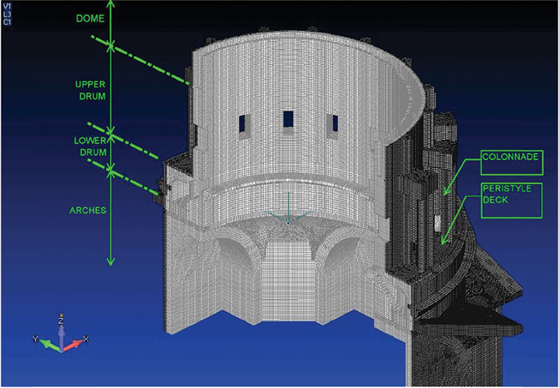
Figure 8: Finite element model of upper drum/lower drum/arches.
Iterative analyses was used to evaluate deterioration and distress. The analysis started by modeling the structure without cracks or deterioration. Then cracks were introduced at areas with concentrated tensile stresses to see how the condition redistributes forces in the structure. A process of lengthening cracks was repeated, which redistributed forces until the masonry tensile stresses were well below the tensile capacities. The stresses, deflections, and stability of the structure were then reviewed. A similar iterative approach was used to evaluate the effect deterioration has on the structure.
Results
The results of the analysis correlated well with the observed conditions of the masonry construction. Under gravity loads, the model showed tensile stresses that exceed tested capacities where there were cracks in the actual brick masonry (Figure 9). The results of the iterative analysis demonstrated redistribution of tensile and compressive stresses with reasonable magnitudes and continuity of load path through the masonry of the lower drum, even with cracks and deterioration. Consequently, the cracking and deterioration were not cause for concern about the structural integrity of the lower drum. Finite element analyses raised confidence levels in this conclusion.
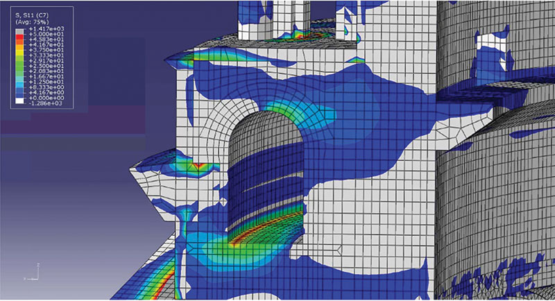
Figure 9: Radial tensile stress in lower drum.
Continued masonry deterioration and propagation of masonry cracks can increase the stresses in the remaining competent masonry, cause further deformations of the lower drum, and increase the width of the circumferential cracks in the crown of the tunnel. Since moisture likely contributed to existing deterioration, it was prudent to continue a planned program of masonry repairs to protect the structure from moisture intrusion along with recommending future monitoring.
Conclusions
- Load paths of monumental masonry structures are inherently complicated. These complications are caused by initial highly indeterminate construction geometries and the fact that actual load paths evolve due to load redistribution in response to deterioration, distress, and movement. Therefore, these load paths cannot easily be resolved with classical hand calculation approaches.
- Finite element modeling can be a powerful tool to help the investigator evaluate load paths and structural performance of a monumental masonry structure. The work at the Pennsylvania Capitol showed that the results of finite element modeling correlate well with actual performance.
- The success of the finite element modeling depends on the diligent construction of the model and its boundary conditions, and the amount and quality of actual building performance data, such as material properties derived by testing.
- As with any analytical technique, the results of the finite element model must be carefully augmented by, and scrutinized against, the results of other approaches. Finite element analysis is but one of several techniques, the most important of which is the investigator’s own engineering judgment, that must be deployed in the evaluation of monumental masonry structures.
The authors acknowledge the support of the State of Pennsylvania’s Department of General Services, the architecture firm of Perfido Weiskopf Wagstaff & Goettel, and the partners of Simpson Gumpertz & Heger.▪