
American Iron and Steel Institute (AISI) cold-formed steel design and construction standards are developed and maintained by the AISI Committee on Specifications for the Design of Cold-Formed Steel Structural Members and the AISI Committee on Framing Standards. The operation of both Committees follow the “Essential Requirements: Due process requirements for American National Standards” established by American National Standards Institute. All the standards developed by the Committees go through ANSI conducted public review and approval processes to become American National Standards (ANS). All AISI standards published in 2007 were either reaffirmed as the ANS or published as a new edition in 2012. A complete list of AISI standards and their status is given in Table 1.
Table 1: AISI Standards Status.
This article provides an overview of major technical changes and additions that were included in the AISI standards and supplements published in 2012.
1) Technical Changes and Additions in AISI S100, North American Specification for the Design of Cold-Formed Steel Structural Members, 2012 Edition
a) Section A2, Material. To facilitate the selection of appropriate steel grades, in the 2012 edition, the list of applicable steels has been grouped by their minimum elongation requirements over a two-inch (50-mm) gage length: the specified minimum elongation of 10 percent or greater, 3 percent to less than 10 percent, and less than 3 percent. The permitted uses and restrictions are then specified for each of the groups. For example, the steels with a specified minimum elongation of 10 percent or greater can be used without restriction as long as the steels meet the requirements specified in Section A2.3.1. Steels with elongation from 3 percent to 10 percent can be used with reduced yield stress and tensile strength as specified in Section A2.3.2. Steels with specified minimum less than 3 percent may be used in multiple web configurations such as roofing, siding and floor decking provided the adjustments specified in Section A2.3.3 are met. Additionally, a new material standard ASTM A1063/A1063M, Standard Specification for Steel Sheet, Twin Roll Cast, Zinc-coated (Galvanized) by the Hot-Dip Process, was added in 2012.
b) Section B1.3, Corner Radius-to-Thickness Ratios. Research indicated that the provisions in Chapter B may become unconservative when predicting the effective width if the corner radius-to-thickness ratio, R/t, is larger than 10 (Figure 1). Thus, the effective width equations in Chapter B are restricted to R/t less than or equal to 10. However, the design engineer may use cross-sections having radius-to-thickness ratios greater than 10 by using a rational engineering analysis method such as the Direct Strength Method or a prescriptive method applicable for 10 < R/t ≤ 20 that is provided in AISI S100 Commentary Section B1.3.
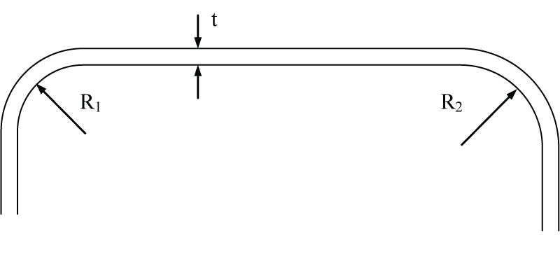
Figure 1: Corner radius.
c) Section B2.5, Uniformly Compressed Elements Restrained by Intermittent Connections. This section is used to determine the effective widths for elements, such as cellular decks, that are restrained by intermittent connections (Figure 2). The added provisions will enable increased moment capacities for some cellular deck profiles.
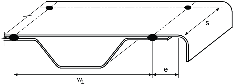
Figure 2: Effective width at edge stiffener.
d) Section C3.6, Combined Bending and Torsional Loading. This section takes into consideration the torsional effect for singly or doubly symmetric section members subjected to bending and torsional loading by applying a reduction factor, R, to the nominal flexural strength determined based on initial yielding. The reduction factor, R, was revised in 2012:
R = [pmath]{f_{bending underline{ }max}}/{f_bending + f_torsion}[/pmath] ≤ 1 Eq. (1)
where fbending_max = Bending stress at extreme fiber, taken on the same side of the neutral axis as fbending, fbending = Bending stress at location in cross-section where combined bending and torsion stress is maximum, ftorsion = Torsional warping stress at location in cross-section where combined bending and torsion stress is maximum. Eq. (1) enables one to accommodate situations where the maximum stress due to combined bending and torsional warping occurs at the tip of a flange stiffener, and at web-flange or flange-lip junctions.
e) Section D3.3, Bracing of Axially Loaded Compression Members. The revised provisions should produce a more reliable and economic design of bracing to a compression member because the brace force and stiffness are now calculated based on the axial load in the column. The required brace force and stiffness can also be determined using the frame analysis that takes into consideration second-order effects (i.e., considering both P-[pmath]delta[/pmath] and P-∆ effects).
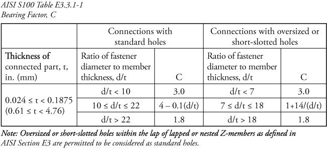
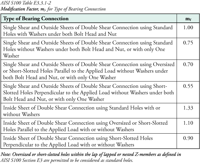
f) Section E3, Bolted Connections. Provisions are added to determine the strength of bolted connections for slotted or oversized holes. The slotted or oversized hole sizes are defined in AISI Table E3a. The bearing strength, Pn, without consideration of bolt hole deformation can be determined from:
Pn = C mf d t Fu Eq. (2)
where C = Coefficient determined in accordance with AISI S100 Table E3.3.1-1; mf = Modification factor for type of bearing connection determined according to AISI S100 Table E3.3.1-2; d = Nominal bolt diameter; t = Uncoated sheet thickness; and Fu = Tensile strength of sheet as defined in AISI S100 Section A2.1 or A2.2.
g) Section E3.4, Shear and Tension in Bolts. The nominal tensile and shear strengths of bolts were updated to be consistent with the values in the AISC Specification.
h) Section E4.5, Combined Shear and Tension. This section now includes three combined shear and tension checks for screw connections: combined shear and pull-over, combined shear and pull-out, and screw combined shear and tension, where combined shear and pull-out and combined shear and tension are newly added:
For combined shear and pull-out:
[pmath]Q/{P_ns}[/pmath] + [pmath]T/{P_not}[/pmath] ≤ [pmath]1.15/Ω[/pmath] For ASD Eq. (3)
and
[pmath]{Q_u}/{P_ns}[/pmath] + [pmath]{T_u}/{P_not}[/pmath] ≤ 1.15[pmath]phi[/pmath] For LRFD Eq. (4)
where Q, Qu, and T, Tu = Shear and tension forces, respectively, determined in accordance with ASD or LRFD load combinations; Pns = Nominal shear strength of sheet per fastener = 4.2(t[pmath]matrix{2}{1}{3 2}[/pmath]d)1/2Fu2; and Pnot = Nominal pull-out strength of sheet per fastener = 0.85tcdFu2; Ω = Safety factor = 2.55; f = Resistance factor = 0.60; t2 =Thickness of member not in contact with crew head or washer, Fu2 = Yield stress of t2; d = Nominal diameter of screw; and tc = Lesser of depth of penetration and thickness of t2. The equations are applicable with the following requirements satisfied:
(1) 0.0297 in. ≤ t2 ≤ 0.0724 in.,
(2) No. 8, 10, 12, or 14 self-drilling screws with or without washers,
(3) Fu2 ≤ 121 ksi, and
(4) 1.0 ≤ Fu/Fy ≤ 1.62.
For screw combined shear and tension:
[pmath]T/{P_ts}[/pmath] + [pmath]V/{P_ss}[/pmath] ≤ [pmath]1.3/Ω[/pmath] For ASD
and
[pmath]{T_u}/{P_ts}[/pmath] + [pmath]{V_u}/{P_ss}[/pmath] ≤ 1.3[pmath]phi[/pmath] For LRFD
where Pts = Nominal tension strength of screw as reported by manufacturer or determined by independent laboratory testing; Pss = Nominal shear strength of screw as reported by manufacturer or determined by independent laboratory testing; Ω = Safety factor = 3.0; and [pmath]phi[/pmath] = Resistance factor = 0.5.
i) Section E5, Power Actuated Fasteners. Comprehensive design equations were adopted for the design of connections using power actuated fasteners. Although the design equations address potential limit states such as shearing of the sheet or the connector, tension pull-over of the sheet or tension pull-out of the fastener, manufacturer’s published design values are still permitted.
j) Appendix 1, Design of Cold-Formed Steel Structural Members Using the Direct Strength Methods. By using software, Appendix 1 provides a rational engineering analysis approach for determining strengths of cold-formed steel members. Provisions were added for members with holes, web shear strength and inelastic reserve capacity.
2) Technical Changes in AISI S200-12, North American Standard for Cold-Formed Steel Framing-General Provisions, and AISI S201-12, North American Standard for Cold-Formed Steel Framing-Product Data
These two standards were reorganized as part of a code synchronization effort to eliminate duplications and redundancy, as well as to clear any ambiguities among AISI and ASTM standards, and building codes. Specific areas considered include: material thickness, physical dimensions and tolerance, mechanical properties, coatings-corrosion resistance, and labeling requirements. Another major reorganization was due to the development of a new AISI S220, North American Standard for Cold-Formed Steel Framing – Nonstructural Members. The design provisions related to nonstructural members were moved from AISI S200 and AISI S201 to AISI S220. Consequently, AISI S200 and AISI S201 are written for structural members, while AISI S220 is specifically for nonstructural members.
3) Technical Changes in AISI S214, North American Standard for Cold-Formed Steel Framing – Truss Design
The major change for this standard is related to the provisions of truss responsibilities. Those provisions were extracted from AISI S202, Code of Standard Practice for Cold-Formed Steel Structural Framing, and added to AISI S214.
4) Technical Changes to AISI S211, North American Standard for Cold-Formed Steel Framing – Wall Stud Design
Supplement 1 to AISI S211 includes updates of the referenced standards, and deletions of the provisions related to nonstructural members.
5) Technical Changes to AISI S230, Standard for Cold-Formed Steel Framing – Prescriptive Method for One and Two Family Dwellings
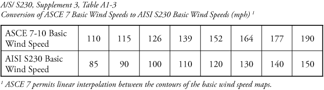
With the introduction of ASCE 7-10, an equivalent wind load table was added in Supplement 3 that converts ASCE 7-10 basic wind speeds to AISI S230 basic wind speeds.
6) AISI S220, North American Standard for Cold-Formed Steel Framing-Nonstructural Members
To help clearly delineate and eliminate confusion between the requirements for cold-formed steel structural members and nonstructural members, AISI S220 was developed in 2011 specifically for the design and installation of cold-formed steel nonstructural members in buildings. AISI S220 should be able to eliminate the confusing industry reference to “equivalent” or “EQ” sections if all nonstructural profiles are designed and designated in accordance with AISI S220. In addition, AISI S220 clarified the definition of nonstructural member as “A member in a steel-framed system that is not a part of the gravity load resisting system, lateral force resisting system or building envelope.” Examples of a nonstructural members include, but are not limited to, members in a steel framed system which is limited to a transverse (out-of-plane) load of not more than 10 lb/ft2, a superimposed axial load, exclusive of sheathing materials, of not more than 100 lb/ft, or a superimposed load of not more than 200 pounds. The strength of the nonstructural members may be determined by either non-composite or composite design approach. The non-composite assembly design approach utilizes the design provisions of AISI S100 but with adjusted safety and resistance factors, ΩN = 0.9Ω; and [pmath]phi[/pmath]N = 1.1[pmath]phi[/pmath]; where Ω, [pmath]phi[/pmath] = Safety and resistance factors from relevant section of AISI S100; and ΩN, [pmath]phi[/pmath]N = Corresponding safety and resistance factors for nonstructural members. The non-composite assembly design approach can also be done via testing and, with the test results, evaluated in accordance with AISI S100 Chapter F but with a target reliability index, β0 = 1.6. For composite assembly design approach is generally accomplished by testing and, with the test results, evaluated in accordance with AISI S100 Chapter F. Detailed discussion on nonstructural design and installation can be found from a separate paper, Design of Nonstructural Members in Accordance with AISI S220, by R. A. LaBoube, et al (February 2013, STRUCTURE magazine).▪