
Engineering advancements can have a major impact on the end design of buildings, improving their aesthetics and therefore their marketability. Cutting edge techniques employed for a six-story tilt-up speculative office building near Houston prove that advancements in the field of tilt-up concrete construction are having a positive impact on real estate profitability.
When it comes to commercial real estate, having a “Class A” label can greatly increase the rents that a property can command. The Building Owners and Managers Association (BOMA), an international organization that manages measurement standards for buildings, defines Class A properties as the “most prestigious buildings competing for premier office users with rents above average for the area. Buildings have high quality standard finishes, state of the art systems, exceptional accessibility and a definite market presence.” Furthermore, the architecture of a Class A building has to be a cut above the utilitarian ‘box.’
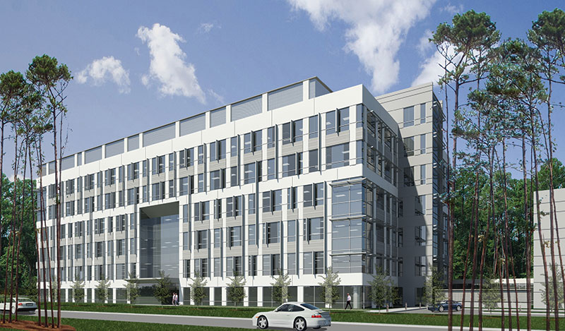
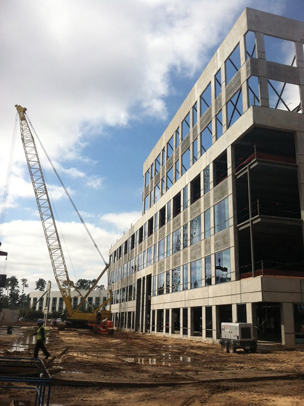
Southwest corner. Courtesy of Powers Brown Architecture.
The Sierra Pines II building represents Phase 2 of the Reserve at Sierra Pines project. It is situated on a four-acre site within The Woodlands, one of America’s first master-planned communities. Located in suburban Houston, Texas, The Woodlands covers 28,000 acres and includes 7,000 acres of protected green space, making it a highly marketable location.
Before it could qualify as a Class A property, however, Sierra Pines II had to achieve architectural distinction. To do so economically, tilt-up concrete construction was selected. Once seen as a method suitable only for warehouses and other lower-end structures, tilt-up has proven itself as appropriate for high quality buildings and distinguished architectural design. At six stories, Sierra Pines II will be the tallest building constructed with load-bearing tilt-up concrete in Texas.
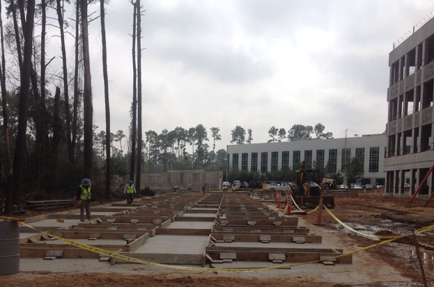
Phase 2 east side formed panels. Courtesy of E.E. Reed Construction, L.P.
Defying ‘The Box’
The 154,213-square-foot Sierra Pines II building is vertical in its proportions, which differentiates it from many tilt-up projects. Potential tenants within The Woodlands market typically do not require the large footprint office buildings of the recent past, and the 25,000 square-foot floor plates of Sierra Pines II make for better views and provide more daylight for the building’s occupants. Rising property values also play into the equation; as the cost of land increases, building higher makes more and more sense.
Four + Two
The building’s six-story walls are composed of a lower four-story panel measuring 58 feet 11 inches tall with a two-story panel measuring 31 feet 2 inches in height stacked on top. While the 90+ foot tall elevation could theoretically have been engineered utilizing single panels, site constraints, namely the available casting area, restricted the height of the panels.
The four-story panels were cast on the building slab and adjacent casting beds, strategically located to preserve the soaring pine trees that make the site so attractive. Once the four-story panels were lifted into place, the two-story panels were cast. While two different casting sequences are not as efficient as one, this approach delivered several advantages for this project. First, it allowed for a relatively slender six-story tilt-up building to be constructed on a very tight site. Dividing the wall panels into two sections gave the designers the ability to reduce the thickness of the two-story panels. The lower four-story panels are 14 inches thick while the upper two-story panels are only 7½ inches thick.
The major architectural advantage, which ended up having a dramatic effect on the rhythm of the façade, was the ability to shift the panel joints so that the panels are not aligned vertically from the bottom of the building to the top. This allowed the entire fenestration pattern to shift, breaking down the scale of the building. The shift in panel joints had structural implications as well. The load path is disrupted at the shift, creating highly concentrated vertical and lateral loads over openings in the lower four-story panel. These loads are transferred into the fourth story headers through a series of embeds with weld plate connections, then on to the vertical panel legs by reinforcement designed to handle the shear and flexure resulting from this load transfer. The design takes into account the rigidity of the beam and column elements in the panel; as a result, shear stirrups and ties are incorporated into the panel in addition to the normal vertical and horizontal reinforcement. Finally, the shift in joint location allowed for a quick erection process because there were fewer alignment challenges.
By separating the panel legs with openings instead of having them side by side, the legs appear much thinner and lighter. The panel joint itself is broken by the openings at each level, further eliminating the perception of a large panel.
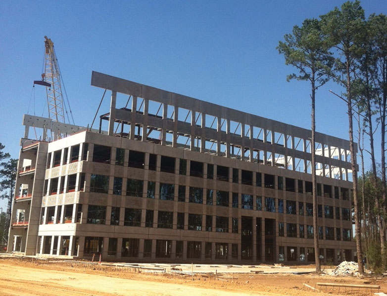
Overall building perspective looking at the east face as viewed from the parking garage. Courtesy of Big 4 Steel Services, L.P.
Building the Tallest Load-Bearing Tilt-Up in Texas
Due to soil conditions, it was necessary to extend foundation bearing more than 6 feet below finished grade. To keep the panels from growing any taller, thereby saving casting space, a 5-foot tall poured-in-place concrete stem wall extends from the top of the footing to 1 foot below the finished floor. Welded plate connections, similar to those used between the lower and upper panels, connect the four-story panels to the concrete stem wall.
For a variety of structural reasons, welded plate panel-to-panel connections are utilized throughout the structure in lieu of grouted sleeve connections or simple plate connections with expansion anchors. At many locations, panel joints occur above openings, creating cantilevers. The most dramatic joints occur at the ends of the building, where multi-story openings wrap the corners of the building. The cantilevered header elements form a mitered corner condition. The panels are connected at the corner to stabilize the somewhat delicate arms of the panel and connected on the other side of the panel to reduce overturning forces in the plane of the wall. The building is designed to withstand 110 mph three-second gusts per the requirements of the 2009 International Building Code (IBC) using ASCE 7-05 for the wind design. While greater than most inland locations, this wind load is typical for the region and contributed to the need to connect panels to one another across the panel joints.
Tilt-up panels, because of their composition and size, often provide the necessary lateral stability for the building as shear walls. However, because of the larger wind loads, an architectural mechanical screen on the roof, numerous large openings and the slender aspect ratio of the building, diagonal steel bracing is incorporated at two interior column lines.
The main entrance panel presented several engineering challenges. The upturned “U” shaped panel is 58 feet 11 inches tall and almost 40 feet wide, with a four-story tall (54 feet 11 inches) 30-foot wide opening. On the outside edges of the panel, small, cantilevered fingers extend out to form half of the adjacent panel openings at each floor. The 14-inch thick panel is designed with integral 16-inch returns along the large center opening for added rigidity. According to the contractor, this panel was the most difficult to tilt.
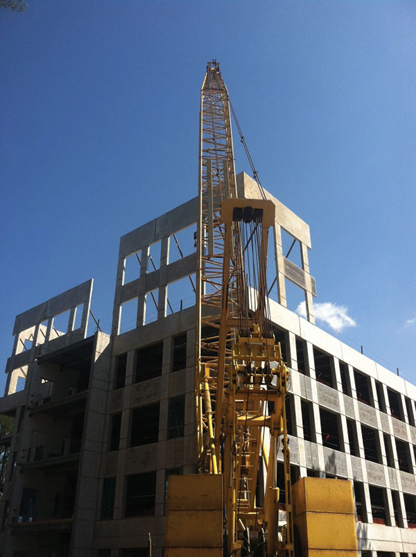
Erection of the upper panels on the northwest corner. Courtesy of Big 4 Steel Services, L.P.
Once designed, innovative thinking on the construction side furthered the project’s success. For example, the project had originally been engineered using the 2012 TCA Guideline for Temporary Wind Bracing of Tilt-Up Concrete Panels during Construction to utilize three 52-foot tall braces per lower panel. By switching to higher-strength braces, and helical ground anchors to take full advantage of the capacity of those braces, it was possible to eliminate one brace per panel, or 33 percent of the braces.
In addition to reducing the number of braces per panel, the team was able to reduce the length of the braces from 52 feet to 42 feet. With the original three-brace configuration and the location of openings within the panels, taller braces were required to get above the openings. With only two braces per panel, they could be located between openings at a lower elevation. This presented additional savings on freighting. On a very tight site with panels braced to the exterior, this also meant additional room around the perimeter because the shorter braces could be anchored closer to the structure. Once the concrete slabs of the second through fifth floor were in place, these braces were even removed prior to erecting the upper panels, thereby freeing up the room necessary for the panel erection crane to traverse the perimeter of the building.
Getting the underground utilities in place early was critical to the process. Because of the tight site, the vast majority of space surrounding the building was needed for casting beds and braces during construction. Both underground utilities and helical brace anchors had to be placed strategically to avoid conflicts.
Erection of the upper panels on the east face as viewed from the northeast corner. Courtesy of Big 4 Steel Services, L.P.
The project was divided along its east/west axis for the purpose of construction sequencing. Concrete placement for the south half of floors two through five was a focus for the team as this allowed for the removal of the braces along the south of the building, thereby relieving site congestion. With these floors constructed, crews were able to begin interior framing and worked to rough-in the vast majority of the mechanical, electrical and plumbing on the south side while concrete placement on the north half continued. The internal core steel structure for floors five and six was also in place before the upper panels were lifted into place.
Construction started at the end of September 2013 and the building will be turned over to the developer in August 2014.
What Will This Mean for the Building Industry?
As tilt-up construction pushes the height envelope across the nation, office buildings are likely to be among the earliest adopters in terms of building type. For now, six stories is the typical ‘limit’ for which load-bearing tilt-up construction is specified, mostly due to the limitations of equipment and bracing. For taller buildings, conventional construction using tilt-up construction as cladding panels offers an economical solution.
Taller buildings will be possible as the design and construction communities continue to experiment with stacked panel projects, developing more effective bracing arrangements and stacking configurations.▪