
By Steven G. Judd, CE, SE, CBS
Click here to view the article with images in the digital flipbook.
Although reinforced hollow clay masonry (RHCM) represents a small portion of structural masonry design in the United States and Canada, RHCM has high strength which makes it very suitable and desirable for high demand facilities, such as tornado shelters. There are over 100 times more structural concrete masonry unit producers as there are structural clay masonry producers in the U.S. and Canada, which is one reason why most facilities constructed with structural masonry tend to be constructed with concrete masonry units (CMU). The other drawback to the use of hollow clay masonry (HCM) is an engineer’s lack of knowledge and familiarity with the HCM material. This article helps bridge that lack of knowledge.
Please note this article references The Masonry Society’s TMS 402/602-16, Building Code Requirements and Specification for Masonry Structures. Where different, TMS 402/602-22 items will be noted in brackets, thus: [ ]. The American Society of Civil Engineers’ ASCE 7 -16, Minimum Design Loads and Associated Criteria for Buildings and Other Structures, is also the standard used.
Introduction
A brief comparison: Concrete block can easily and regularly be produced with compressive unit strengths of 3,250 pounds per square inch (psi), which equates to a wall assembly compressive design strength (f’m) of 2,500 psi. Most manufacturers of HCM produce material with average gross net area compressive strength of 9,000 psi up to, and exceeding 18,000 psi, which far exceeds the compressive strength of concrete masonry units, and generally produce units that can be designed for f’m of 3,500 psi or 4,000 psi—without the need for prism testing. Design strengths (f’m) higher than 4,000 psi can be achieved if needed, but prism testing would be required.
In general, the higher f’m provided by RHCM can produce thinner walls for a given height and applied loads, or taller walls with a given unit depth or wall thickness. RHCM is uniquely suited for tornado shelters made with structural masonry to provide the thinnest—sans pilasters—walls possible in structural masonry. (Note: the use of strategically placed pilasters can reduce the wall thickness.)
Wall assembly compressive design strengths (f’m) based on the average unit net area compressive strength, combined with mortar of different types, can be found in TMS 602 § 1.4-B-2-a, Table 1 (for HCM). Type S mortar is most often recommended for structural masonry and is one of the variables in the table.
Also, as a preamble to an actual design example provided later in this article, it is worth noting that the 2021 International Building Code (IBC) and later codes have specific tornado wind (WT) design requirements and design load cases that are different than the typical wind design pressures and load cases from previous code editions. These tornado wind load cases, which must be checked, apply to all facilities east of the Rocky Mountains. These tornado wind design requirements in ASCE 7 are considered to be “pass by” or “near miss” scenarios and are not appropriate or even applicable for tornado (or hurricane) shelters. For that special class of facilities, one must use the International Code Council’s ICC 500, Standard for the Design and Construction of Storm Shelters.
Case Study Parameters
Wind design pressures used for tornado shelter wall designs may be 15 to 20 times higher than wind design pressures for typical or standard single-story buildings. In some cases, tornado wind design pressures can exceed 200 pounds for square foot (psf). For the demand generated from those extreme wind design pressures, HCM having roughly double the f’m, as compared to CMU, will prove to be an appropriate choice.
The case study illustrating the capability of RHCM focuses on a community tornado shelter with outside dimensions of 100 feet by 70 feet and day-to-day use as a gymnasium for a school. The walls are 28-feet-8-inches tall from the interior floor to roof. There is no parapet. The flat (shallow sloped) roof system is comprised of open web steel joints spanning the 70-foot width, spaced at 4-feet on center supporting a 6-inch thick concrete-on-metal-deck roof. The joist layout starts two feet from the 70-foot end walls. Total roof dead load is 103 psf.
Ten-inch deep HCM units were chosen for the single-wythe wall. The unit size used for this case study was 10 inches deep by 4 inches tall by 16 inches long, (nominal dimensions), called a 10416 unit, with two large rectangular cells adjacent to the end webs, and a single narrow cell in the center (Fig. 1) The design assumes (requires) a fully grouted wall. Wall weight was calculated at 103 psf. The terms “fully grouted” or “solid grouted” (currently used interchangeably in TMS 402/602) allows for voids in the head joints between the mortared face shells (standard mortar bedding) of square ended units (for CMU and HCM) and should allow for the unfilled center cells of HCM and the large head joint voids for CMU units made with “ears” due to recessed end webs. These voids are generally assumed to remain unfilled when using standard coarse grout and standard grouting procedures. The tornado shelter walls were fully grouted to provide the durability needed for tornado shelter projectile impact resistance, per ICC 500, which has been proven via testing by at least one HCM manufacturer. Reinforcing also requires fully grouted walls.
This case study was based on Strength Design (SD) concepts (TMS 402 chapter 9) with f’m = 4,000 psi. The minimum grout strength (f’g) was chosen to equal f’m, so, f’g = 4000 psi, in accordance with TMS 602.
Per ICC 500, the tornado design wind speed (VT) from Figure 304.2(1) was 250 mph; roof live load was 100 psf, to account for wind borne debris landing on the roof; Exposure Category C is prescriptive; Topographic effects Kzt = 1.0; wind directionality factor, Kd = 1.0; gust-effect and internal pressure coefficient, GCpi = +/-0.55 (partially enclosed). This assumed GCpi coefficient may be conservative if the openings are properly designed and constructed for tornado wind and impact resistance, wherein +/- 0.18 is allowed.
The assumed ground elevation for this example is 750 feet above sea level (Ke = 0.97).
For monolithic structural masonry walls, there is some debate as to the most appropriate derivation of the “Effective Wind Area” (EWA) used for Components and Cladding (C&C) design. EWA is part of several nomographs in ASCE 7 used to determine various pressure coefficients. With the amount of reinforcing anticipated in these walls the EWA was chosen to be 2L2/3, or double the minimum suggested (but not required) by the code. [An EWA of 2L2/3 was chosen because a monolithic wall most likely performs more like a plate or membrane for out of plane load distribution than discrete framing members like stud wall framing or roof joist/purlin framing]. For the roof C&C wind pressures EWA of L2/3 was used relative to the discrete roof framing members. EWA for monolith planar masonry walls is not universally interpreted as L2/3, with such variations as L x 6t; L x joint spacing; and/or L2 used by various engineering practitioners.
Main wind force resisting system (MWFRS) wind pressures were used for walls acting as shear walls for wind blowing parallel to the wall, and C&C design wind pressures were used for wind perpendicular to the walls (which were not acting as shear walls for that load case). Maximum negative (suction) out-of-plane (OOP) design wind pressure for C&C design was -219.0 psf; maximum negative OOP design wind pressures for MWFRS design was -174.1 psf. Maximum C&C wind uplift pressure for the roof was -297.0 psf while the maximum wind uplift roof pressure for MWFRS was -160.0 psf.
The 100-foot-long walls were divided into thirds, horizontally, with movement joints; the 70-foot walls were divided in half with movement joints. The maximum design in-plane (IP) shear in the short 70-foot-long end walls derived from MWFRS wind pressures on the 100-foot-long walls was 57.45 kips per wall segment. For the 100-foot-long wall, the IP design wall shear was 24.9 kips per wall segment.
Controlling Design Cases
Two particularly critical load cases for the tornado shelter emerge: 1) the 100-foot-long wall oriented perpendicular to the wind generating the highest C&C OOP suction (leeward side) and roof up-lift with no IP shear, and, 2) the 100-foot-long wall oriented parallel to the wind direction with MWFRS IP shear, while resisting the MWFRS OOP suction pressures and uplift forces on the tributary roof area. In this case, uplift exceeded the gravity loads on the wall, putting the wall into net tension throughout its height. Of course, all code prescribed load cases and load combinations must be checked and satisfied, but the two noted appeared to be the most critical.
Some consideration should be given to the assumed fixity at the base of the wall based on the detailing and construction at the base of the wall. A pinned base would have Mu-p-base = 0.0, and Vu-p-base = wLb/2; a fixed base would have Mu-f-base = wL2b/8, and Vu-f-base = 5wLb/8, where ‘b’ is the effective unit width, or length along the wall being considered, and ‘L’ is the span length. For this case study, a pinned base was assumed. Also, keeping the maximum moment away from the base simplifies the foundation design and will prove to be important when checking dowels.
EleMasonry software was used to facilitate the actual design and code checks. The main wall reinforcing that satisfies the various load combinations is shown in Figure 2.
This is a lot of reinforcing, but the walls are nearly 30-feet tall with extreme winds. Horizontal steel selected was (1) #4 @ 48” o.c. vertically to meet code minimum bar size. The maximum vertical spacing allowed by code is 120 inches. Interestingly, deflection control is a main consideration and impacted the reinforcing selection.
The roof joists attached to the wall and the top courses of masonry must have sufficient tension capacity to resist the extremely large net uplift loads. Special detailing may be necessary to develop the reinforcing in tension at the very top of the wall to resist the roof joist uplift loads at their supports. (This could be steel bearing plates with fusion welded deformed bar anchors extending a sufficient length downward into the wall to lap with the vertical wall reinforcing. Another special detail could include also creating a 24-inch deep “beam-in-the-wall” at the top of the wall to facilitate developing hold-down reinforcing and spreading the joist reactions laterally would be a wise choice). Using #3 180-degree hairpin dowels at the top of the wall to match the vertical reinforcing, placed to engage the top horizontal steel, is a good design choice.
Out-of-Plane Base Shear in Walls
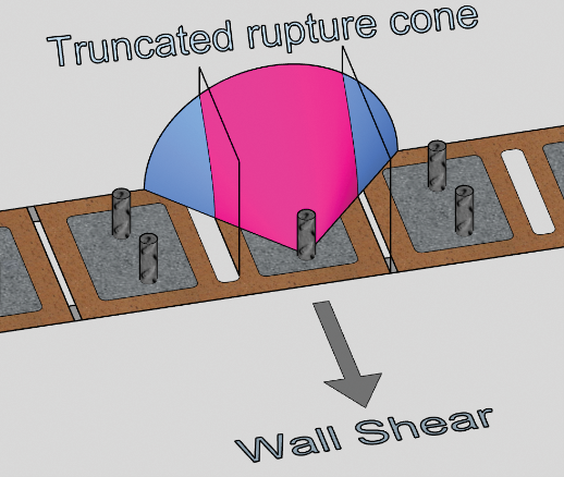
For most design cases, the OOP wind design pressures creating OOP shear at the base of the wall is generally not much of a design consideration, but it is something that requires some specific attention for tornado shelters—especially for tall walls due to the high OOP C&C wind design pressure. Procedures developed for “headed and bent-bar anchor bolt” design were used to check the wall base connection for OOP shear, substituting the foundation rebar dowels for anchor bolts. This is made somewhat more complicated because the center cell of the HCM units will likely be, and should be assumed to be, unfilled, as previously noted. This center cell void and head joint void can create a truncated shear cone, depending on dowel placement, for masonry breakout design checks, which is one of the two primary masonry strength items to check at the base of the wall for OOP forces. This truncated cone “devalues” the masonry shear breakout strength at the base connection of the wall. The other critical masonry strength design check is crushing of the masonry material (crushing the grout, actually) as the foundation dowels bear against the grout in the filled cells. For these checks, one generally assumes that the foundation dowels will match the vertical reinforcing and will be well developed into the foundation, most likely via hooks into the footings or pile caps, and well developed by sufficient development or lap lengths into the wall above the foundation. For this case study, prying failure and pull-out failure were not an issue. Lastly the rebar shear strength must be checked.
If all the vertical reinforcing is doweled into the foundation, it would be difficult to consider the base of the wall as a pinned connection. Consequently, a single #7 dowel was assumed, centered in the cell, at 16” o.c. as the sole reinforcing connection between the wall and foundation to represent a pinned base most closely.For the rebar dowel centered in the cell at the base of the wall shown in Figure 3, the rupture cone for the 10-inch deep units would be a full 45-degree half cone with a surface area of 44.08 in2. (For dowels placed at the maximum distance from the rupture face of the unit shown in Figure 4, the rupture cone would be truncated (devalued) as it passes through the plane of the head joint void and the plane of the center cell void – but still greater than the 44.08 in2.) The capacity reduction factor (Φ) for shear is 0.50 for masonry modes of anchor failure (breakout and crushing), and 0.9 [0.65] for steel modes of failure (9.1.4.1). Using the single #7 rebar dowel centered in the cell (left image above) the masonry breakout capacity (Eqn. 9-6 [9-4]) was ΦVnbOOP = 5.6 kips. The masonry crushing capacity (Eqn. 9-7 [9-5]) was ΦVncOOP = 6.1 kips and the rebar shear capacity (Eqn 9-9 [9-7]) was ΦVnsOOP = 19.4 [14.0] kips, assuming full capacity of the steel.
The C&C Zone 5 wind pressure at the pinned base of the wall generated an OOP shear force of Vu = 4.2 kips at 16” o.c. The OOP shear capacities previously noted for the #7 dowels at 16” o.c. indicated that there was sufficient capacity at the base of the wall to resist the C&C OOP shear demand for the “non-MWFRS” walls – walls perpendicular to the wind direction. Utilization ratio = 0.22.
Checking combined wind effects: Some masonry design programs will only check IP and OOP loadings as separate load conditions, individually. For the MWFRS walls, IP and OOP forces act simultaneously so the design must account for those superimposed effects—basically a biaxial bending issue, plus shear, both IP and OOP shear. Combinations and utilization ratios vary with height, so several checks should be made to confirm that adequate strength is provided at various wall heights. So, after said checks were performed, the design was deemed adequate.
Also, consider checking shear friction at critical heights of the wall to ensure that uplift is not impacting the shear strength detrimentally. The default coefficient of friction, μ, value is 0.7.
Conclusion
The intent of this case study was to show that RHCM can be designed for tall walls under extreme wind loadings from tornados due to the inherent strength advantage of RHCM. Additionally, this case study provided an opportunity to clarify the terms “fully grouted” and “solid grouted,” which may not be what most designers assume. Further, the question of determining the EWA for monolithic walls and wall elements is worth an additional discussion since there seems to be varying interpretations and little consensus of what is the “correct” EWA formula for monolithic walls.
By way of comparison, if this particular facility was to be constructed with CMU, using units with a net area compressive strength of 3,250 psi, the wall thickness would need to be a minimum of 12-inches deep; plus, for the finished brick appearance, which is one of the design imperatives, brick veneer or thin brick would need to be added to the CMU. A single wythe RHCM wall will always be less expensive than brick over CMU due to the reduction of materials and, most importantly, the reduction of labor to install one wythe versus two. Secondary benefits are more interior space and thinner/smaller foundations. [In general, walls designed for CMU can be swapped to HCM without any redesign, but the full efficiencies of the higher strength HCM material will be somewhat limited.]
HCM is a material that has the three building qualities espoused by Vitruvius – Firmitas, Utilitas, and Venustas, which means strength, utility/usefulness, and beauty. Consequently, RHCM can be used effectively to construct buildings with those same three qualities, especially for buildings with extremely high wind design pressures—like tornado shelters. Where tornado safety is a concern, building with RHCM is a viable solution. For the safety conscious, RHCM also has proven performance via testing for tornado driven projectiles, ballistic impact, and fire-resistive ratings up to four hours—for 8-inch deep units in a filled assembly. RHCM is an excellent choice where safety or protection of valuable assets is a design imperative. ■
About the Author
Steven G. Judd, CE, SE, CBS is the Technical Director of Interstate Brick, a Western U.S. brick manufacturer. He is current Chair of several committees and task groups in Western States Clay Products Association, The Masonry Society, and Brick Industries Association, and is active in various other committees in those organizations as well as in ASTM committees and task groups related to masonry.
The author would like to recognize and give special thanks to John Hochwalt of KPFF Engineering, Seattle, Washington, for insight and assistance regarding shear in masonry walls under net tension.