
By Jared S. Hudson, PE, and Shaun M. Kreidel, SE
Click here to view the article with images in the digital flipbook.
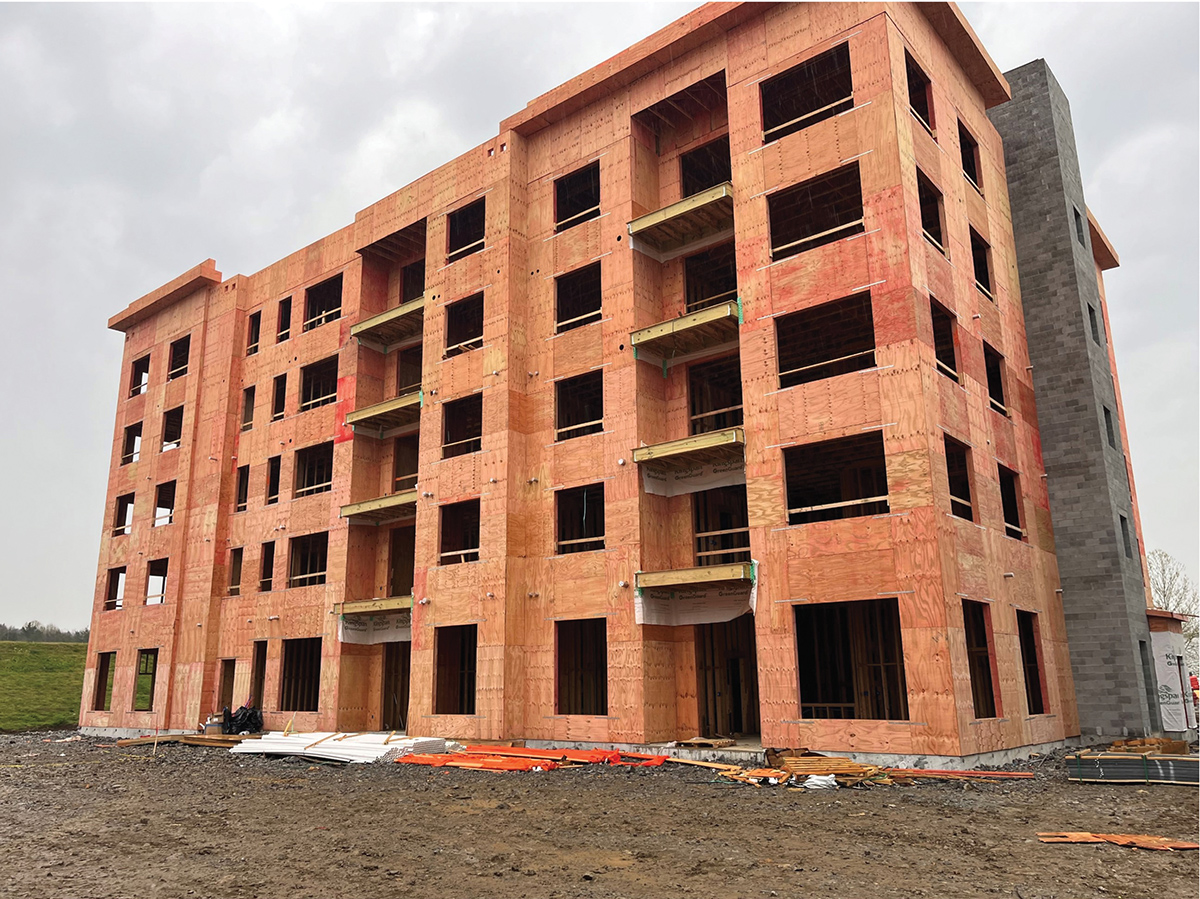
Light frame wood construction is often a desired construction method for low-rise multifamily structures due to readily available labor and materials, speed of construction, sustainability, and relatively low construction costs. A Type V construction classification as defined by the International Building Code (IBC) is commonplace for these structures; however, this construction type is limited to four stories of stacking wood construction. A Type III construction classification allows conventional wood-framed structures to include an additional level, bringing the allowable height to five stories above grade; see Figure 1 for an example of this type of construction.
This construction type may be attractive to developers looking to maximize the occupiable square footage of a defined footprint while taking advantage of the many benefits that come with light-frame wood construction. To facilitate a Type III classification, unique structural and architectural detailing is needed to maintain the strength, stability, and serviceability of the wood-framed structure, as well as to address the applicable fire design requirements. These details are multidisciplinary in nature and require a high level of collaboration between the structural engineer, architect, and builder/developer to ensure that the project meets the owner’s expectations and the building code requirements of the Authority Having Jurisdiction (AHJ).
Depending on the requirements of a given project, practicing engineers may need to investigate certain design aspects that become critical when meeting the requirements of Type III construction. These design considerations include material requirements, fire-resistance rating requirements, the importance of designing for wood shrinkage, and structural detailing strategies to accommodate fire-resistance ratings at the intersection of the floor/roof assemblies and exterior wall assemblies.
Material Requirements
While construction Types I, II, and III all require the use of non-combustible materials at exterior walls, the IBC recognizes the use of fire-retardant-treated (FRT) sawn lumber and FRT wood structural panel (WSP) sheathing as acceptable materials to satisfy the requirement under Type III construction. Practicing engineers should account for FRT lumber and FRT sheathing strength reduction factors due to the treatment process. The strength reduction factors are manufacturer-specific, thus coordination with the architect and builder/developer is recommended if the intended product is unknown.
FRT treatment process results in sheathing strength reduction factors which can decrease both the allowable spans and the lateral strength/stiffness of diaphragms or shear walls. FRT lumber treatment process also affects the structural properties of sawn lumber; the designer may need to augment the wall/header designs to mitigate these effects. Table 1 illustrates the strength reduction factors from two manufacturers of FRT sawn lumber. Assumed in-service temperature of the lumber is an important consideration that may cause variation in structural property values between manufacturers. High in-service temperatures of more than 100 degrees Fahrenheit will correspond to a greater reduction in strength and stiffness when coupled with fire retardant treatment. The engineer should also account for any wood incising reduction factors that might be needed to treat the lumber and consider using lumber that does not require incising to mitigate the amount of strength reduction. All minimum assumed FRT properties should be listed as design assumptions in the contract drawings to ensure that suitable lumber and WSP products are utilized.
A designer may encounter situations where spans or loads require structural properties beyond what FRT lumber alone can provide. At this time, there are no fire-treated engineered wood products on the market (e.g., LVL, PSL, LSL) known to the author. One strategy available to designers is to utilize a flitch beam; a composite beam that consists of FRT wood laminations bolted to a continuous steel plate. The FRT laminations of the composite assembly will maintain the non-combustibility requirement; however, special attention to detailing to adequately conceal the heads of the bolts of the flitch beam assembly will be required. The designer should also consider the expansion of the longitudinal steel due to elevated service temperatures for longer-spanning flitch beams. Another strategy that the designer can employ is the use of rolled steel framing members within the exterior wall. These members may require additional fire protection along with meeting the noncombustible requirements of the code; the project architect should be consulted for additional fire protection requirements of these members.
Fire Rating Requirements
Type III construction requires that exterior load-bearing walls satisfy a 2-hour fire-resistance rating (FRR). If exterior walls can be classified as non-load bearing, the FRR can be reduced to 1-hour for certain occupancies. A 2-hour FRR is usually accomplished by having two interior layers of gypsum board. Over the full perimeter of the structure, the added cost of an additional layer of gypsum board can be substantial. A common industry interpretation of a non-load bearing exterior wall is one that does not support anything but its self-weight and the self-weight of the walls above. The structural designer can strategically run the framing parallel or introduce girder members parallel with the exterior wall to avoid a load bearing situation. In doing so, a FRR of 1 hour can be utilized and thus an extra layer of interior gypsum board can be avoided. This approach and interpretation should be discussed with the project architect and the AHJ during design to ensure compliance with the local building code.
The vertical continuity requirements of the rated exterior wall assembly have been a hotly debated topic between jurisdictions and design professionals, but the requirements have finally been clarified in the 2024 IBC. According to Section 705.6 of the 2024 IBC, the exterior wall FRR shall extend continuously from the top of the foundation/floor system below to the underside of the roof/floor sheathing above.
owever, if the fire separation distance (as defined in the IBC) is greater than 10 feet, the exterior wall FRR is permitted to terminate at the underside of a ceiling (floor or roof) assembly having an equal or greater FRR than the exterior wall. Detailing at the floor levels and the roof level will need to conform to these requirements. Some commonly used detailing strategies that meet these criteria are presented later in this article.
Wood Shrinkage
With taller wood structures, the consideration of expected wood shrinkage becomes critical. Failure to account for the natural shrinkage of the wood structure may be problematic to the performance and serviceability of both in-wall utilities such as rigid pipes, and brittle veneers such as brick. Lateral ties for brittle veneers shall be designed to accommodate the vertical movement anticipated for a given structure. Expansion of veneers such as brick, which absorb moisture and expand over time, should also be accounted for in the vertical allowance of the ties.
Wood shrinkage can also have a large impact on calculated shear wall deflections. Mechanical hold-down deformation is a component of the shear wall deflection equation. At shear walls where hold-downs are utilized, the amount of wood shrinkage between levels is additive to the deformation (elongation) of the hold-down device. To eliminate this effect, the building designer can utilize a take-up device as part of the hold-down assembly to restore hold-down tautness and thus eliminate this source of added shear wall deflection.
Floor Assembly—Exterior Wall Assembly Detailing Strategies
The following subsections present a few common methods for detailing the floor assembly intersection with the exterior wall assembly for this type of construction. These methods have respective advantages and disadvantages which the designer and design team will need to weigh while considering the topics discussed above.
The common thread between all the detailing strategies is maintaining the 2-hour FRR assembly at the wall intersection with the floor system. The chosen details may affect structural member lengths (e.g., wall studs and roof/floor members), bearing conditions, hardware requirements, and blocking/fire caulking requirements. These different detailing approaches will also yield different overall expected wood shrinkage values. The shrinkage of wood parallel to grain (e.g., vertical wall studs) and pre-manufactured wood floor components is negligible when compared to the shrinkage of wood perpendicular to grain (e.g., flat plates). Limiting the total number of flat plates in the exterior wall assembly will therefore minimize the overall expected shrinkage in these structures. For structures particularly sensitive to this shrinkage, it is recommended that the designer lists the anticipated shrinkage values in the construction drawings so that the other members of the design team can coordinate their components and assemblies.
The FRT requirements of the floor system bearing components has been a topic of debate in previous code cycles. The 2024 edition of the IBC, Section 705.7.1, has clarified that the elements of the floor system bearing on the exterior walls and supporting gravity loads from the exterior wall above shall be in accordance with the requirements for interior building elements of Type III construction and are not required to be constructed of FRT lumber; however, the FRR must be extended through the floor cavity. In areas where the 2024 IBC has not been fully adopted, a discussion with the AHJ would be prudent to confirm that this added clarification will be honored by the local jurisdiction.
Platform Framed Construction
In multifamily construction, utilizing bottom-bearing floor systems is commonplace and often preferred as it allows for the use of consistent wall stud lengths and allows for the overlapping and interconnection of wall double top plates. Traditional platform frame construction with floor trusses relies on a continuous ribbon board, which distributes the loads above to the truss verticals and supports the floor sheathing edge. To meet the Type III FRR requirements, the individual floor truss end verticals and ribbon board would need to carry the same FRR as the wall above, which is impractical/uneconomical in most situations as the gypsum board(s) below would need to extend to the underside of the floor sheathing and fire caulking would need to be applied at each truss penetration. To achieve the required FRR, a solid rim board (glulam/mass timber) occupying the full width of the exterior wall assembly can be utilized per Figure 3. The FRR is achieved through the mass and char capabilities of the rim board which would need to be calculated per the provisions in Chapter 16 of the National Design Specification (NDS) for Wood Construction (or the newly released 2024 Fire Design Specification [FDS] for Wood Construction published by the American Wood Council).
The advantages of this detailing approach are consistent wall plate heights across the structure and minimized shrinkage via engineered lumber for the full depth of the floor system. Disadvantages are the added costs associated with the rim board along the full perimeter of the structure and the floor system connection hardware to the rim board, sequencing issues with the placement of the rim board prior to the floor trusses, and added difficulty in placing floor trusses due to lack of exterior bearing.
Semi-Balloon Framed Construction
Another method to frame the intersection of the floor with an exterior wall of a wood structure is using semi-balloon framed wall construction, where the floor system utilizes top chord bearing trusses to bear on the exterior wall below. Like the platform framing method, the vertical support of the exterior wall above shall have a 2-hour FRR; however, for this method, the gypsum board from below can more practically be extended the full height of the wall assembly due to the minimal size of the required penetrations where fire caulking would need to be utilized (Figure 4).
Advantages of this approach are reduced costs associated with truss connection hardware to the exterior wall, the ability to utilize typical rated assemblies to demonstrate the required FRR, and the use of conventional lumber to provide solid blocking to the underside of the floor sheathing above.
Disadvantages are unique exterior wall plate heights relative to the interior ceiling height, limited spans of floor trusses due to the allowable capacity of top chord bearing trusses, and the addition of multiple flat plates into the exterior wall assembly which will increase overall building shrinkage.
Balloon Framed Construction
The final method presented in this article is balloon-framed wall construction, where the top plate of the exterior wall below extends to the underside of the floor sheathing above per Figure 5. For this construction type, the floor trusses are supported by specialty fire wall hangers that utilize a top flange that bears on the exterior wall. Due to the popularity of this approach, these specialty hangers have evolved to allow for the interior gypsum board sheathing to be placed around the installed trusses to achieve the required exterior wall FRR.
Advantages of this approach are flexibility in the sequencing of gypsum installation, lack of additional flat plates within the exterior wall assembly thus limiting overall shrinkage, and a simplified bracing load path of the exterior walls via direct attachment to the floor sheathing. Disadvantages are the coordination of the exterior wall plate heights relative to the interior ceiling height, the potential for additional studs within the exterior wall to facilitate required hanger loads, added costs due to specialty truss connection hardware, and added difficulty in the placement of trusses due to the lack of exterior bearing.
Roof Assembly—Exterior Wall Assembly Detailing Strategies
Similar to the detailing at the floor levels, the detailing strategy at the roof/exterior wall intersection can vary widely by locale and preference of the design team (Figure 6). As stated for the floor framing options, the exterior wall FRR must continue to the underside of the sheathing above. Due to a lack of practical alternatives at the roof, the author’s experience has been that commonly, the roof detailing for these structures consists of direct bearing of the bottom chord of the roof trusses on the exterior wall below. The gypsum board below shall extend to the underside of the roof sheathing; all penetrations in the gypsum board to allow for truss webs, chords and verticals shall be fire caulked to maintain the required FRR. In cases where the exterior wall FRR is 1 hour, the rated assembly is permitted to be terminated at the underside of the 1-hour rated roof assembly.
Conclusion
The structural designer must consider many factors when pressing the limits of conventional wood framing to new heights to ensure appropriate fire-resistance ratings, structural performance, and constructability. Despite the added complexity that comes with Type III construction, it can yield a structure that is cost-competitive with other structural framing materials that have been more traditionally used in midrise construction. Collaboration between members of the design team is essential on multiple fronts to ensure the delivery of a high-quality, code-compliant design while minimizing construction issues and delays. ■
About the Author
Jared S. Hudson, PE, is a practicing project engineer based in the Atlanta office of Mulhern & Kulp Structural Engineering. (jhudson@mulhernkulp.com)
Shaun M. Kreidel, SE, is an Associate Owner and the Atlanta Office Director for Mulhern & Kulp Structural Engineering. (skreidel@mulhernkulp.com)