
By Duane K. Miller
Many welds are evenly loaded: the applied loads are uniformly transferred through the throat and length of the welds. Such welds are easily designed and routinely perform as expected. Other welds, however, are unevenly loaded. One end of the length of the weld may be more severely loaded than the other, or the loading along the weld throat may be non-uniform. The design of these welded connections is more complicated.
Fortunately, design codes dealing with welded connections, such as the American Institute of Steel Construction’s AISC 360, Specification for Structural Steel Buildings, and the American Welding Society’s AWS D1.1, Structural Welding – Steel provide design rules to accommodate unevenly loaded welds. The unfortunate situation is that engineers and detailers involved with the design of welded connections may be unaware of the need to treat such connections in a special manner. When unevenly loaded welds are treated incorrectly, the performance of the welded connection will likely be compromised.
This article summarizes five of the ten most frequently encountered conditions involving unevenly loaded welds. See Part 1 of this article from the February issue of STRUCTURE for Conditions 1 through 5.
Condition 6: Unevenly Loaded Because the Weld Group Is Unevenly Loaded
In many situations, a weld group resists the applied loads. A beam-to-column connection, for example, may consist of groove welds to the flanges and fillet welds to the web. In this case, the weld group consists of horizontal groove welds and vertical fillet welds. Collectively, this weld group resists the moment and shear applied to the connection. However, the various components of the weld group are not evenly loaded. Bending loads the top flange weld in tension and the bottom flange weld in compression. The vertical fillet welds to the beam web resist tension at the top and compression at the bottom, resulting in an unevenly loaded weld group.
There are several ways to deal with unloaded weld groups. One of the easiest ways is to use the AISC Steel Manual approach, as shown in Tables 8-4 through 8-11. The Steel Manual discusses how to use the tables, as well as alternative methods to the tabular approach, such as the instantaneous center of rotation method.
Condition 7: Unevenly Loaded Because the Weld Attaches a Rigid Member to a Flexible Member
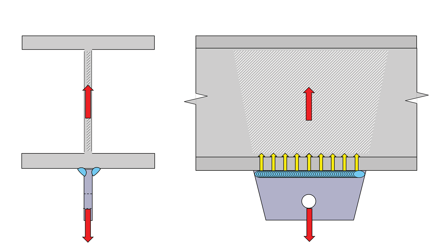
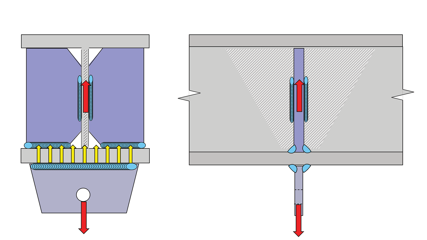
The late Omer W. Blodgett, a pioneer in the design of welded connections and the author’s mentor, famously said, “One of the common oversights is failure to provide a path so a transverse force can enter that part of the member (section) that lies parallel to the force.” A parallel member is stiff, and forces preferentially are attracted to the stiff part. Accordingly, Blodgett encouraged designers and detailers to “provide a path” so the force could be transferred to the stiffer member.
When such a path is not provided, the welded connection is unevenly loaded; more load is transferred through the weld that is connected to the stiffer portion of the member or section, and correspondingly, less is transferred through the weld connected to the flexible part.
As shown in Figure 1, Part A contains an example where the lug is parallel to the beam web. In this case, the transfer of load through the weld is direct and uniform. In Part B, the same lug is welded to the same beam, but the lug is rotated 90 degrees. The loading is no longer uniform as the flange is flexible. Part C provides a possible solution: stiffeners have been added in order to “provide a path” for the force to enter into the parallel member, i.e., into the web.

Condition 8: Unevenly Loaded Because Transverse Welds Are Combined with Longitudinal Welds
Some welded connections involve combinations of longitudinal and transverse welds, as shown in Figure 2. Testing has demonstrated that transverse welds are stronger than longitudinal welds. AISC 360 equation J2-5 addresses this directional strength increase. Transverse fillet welds are generally permitted to be loaded to a 50% higher level than longitudinal fillet welds of the same size and length, made with the same filler metal. The directional strength increase factor (kds) is 1.0 for longitudinal fillets and 1.5 for transverse fillets.
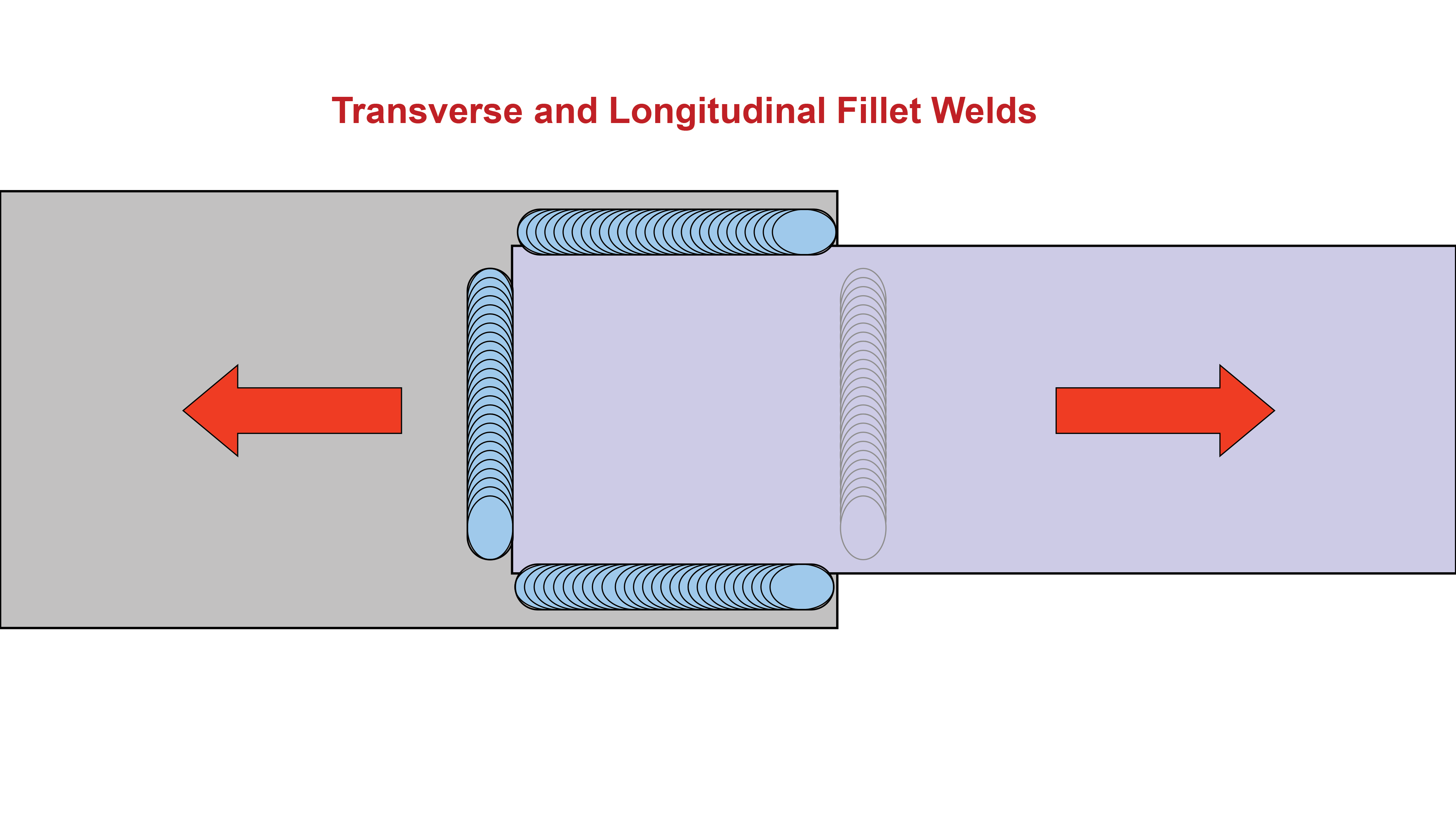
The unevenly loaded condition occurs when transverse and longitudinal welds are combined in one connection. Because of the differential deformation capacity, the transverse weld will assume more load than the longitudinal weld. Therefore, it is not acceptable to directly add the capacity of the longitudinal weld with kds = 1.0 and transverse fillet weld with kds = 1.5. Instead, two conditions should be considered when this unevenly loaded condition exists. First, the capacity of the transverse weld and the longitudinal weld are directly added, assuming kds = 1.0 for both welds (i.e., with no directional increase for the transverse weld). Then, the capacity of the two welds is evaluated using this relationship as shown in equation J2.6 in AISC 360:
Rn = 0.85 FnwAwel + 1.5FnwAwetwhere
Awel = effective area of longitudinally loaded fillet welds, in.2 (mm2)
Awet = effective area of transversely loaded fillet welds, in.2 (mm2)
The capacity of the two welds may be taken as the greater of the two calculations. Depending on the relative capacity of the two different weld orientations, either the normal strength calculation (i.e., with kds = 1.0 for both welds) or the strength calculated in accordance with equation J2.6 may provide the greater capacity.
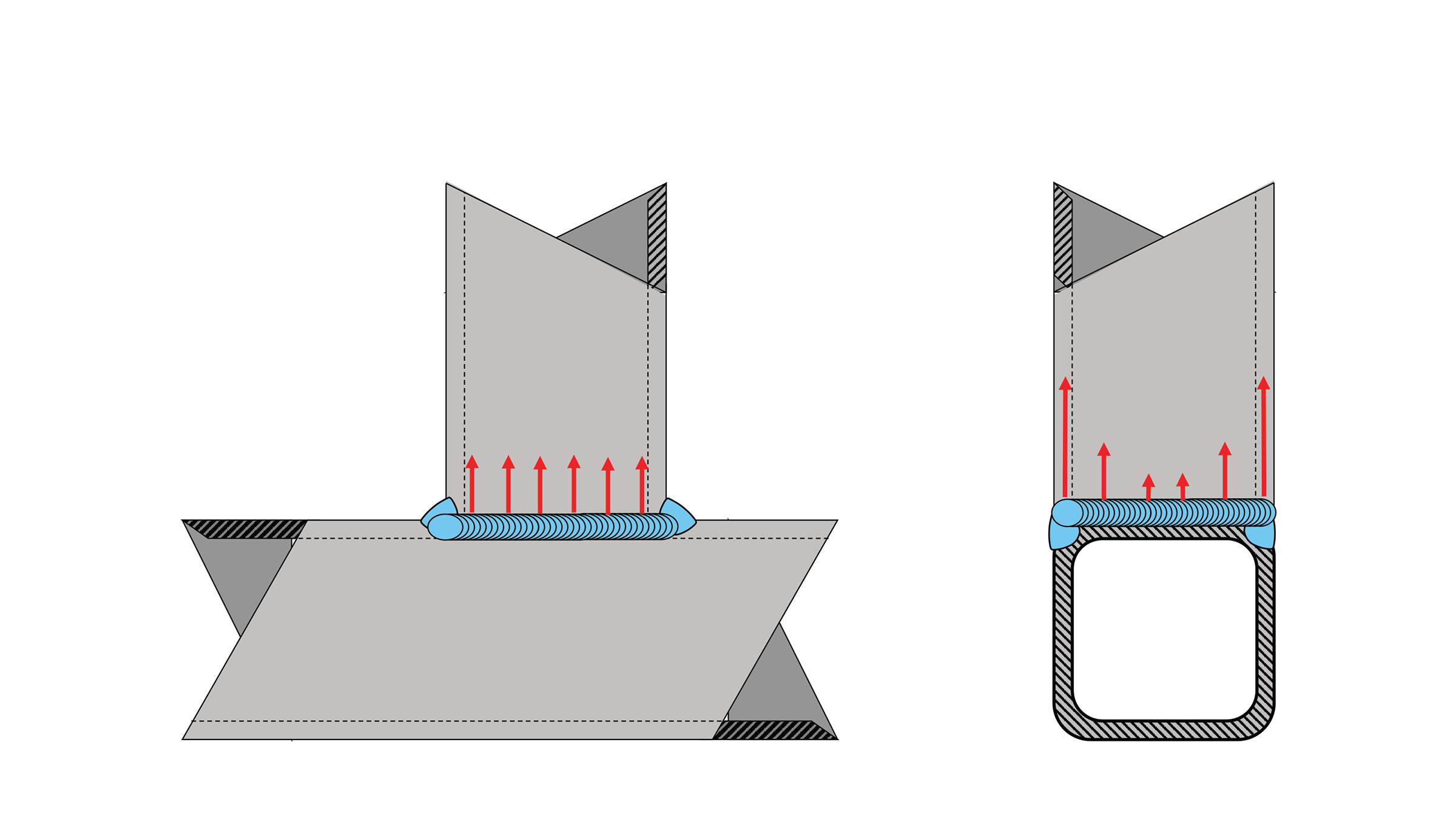
Condition 9: Unevenly Loaded Because the Weld Is Part of a Tubular Connection
When tube-to-tube connections are made, the welds around the tube may be unevenly loaded due to the variable stiffness of the tube. Condition 9 is a specialized example that is related to the previously discussed Condition 7. Consider a square-tube to square-tube connection in a tee configuration, as shown in Figure 3, where the tubes are of the same size. The flare groove weld (i.e., the longitudinal weld) that connects the branch tube to the main tube is evenly loaded along its length. The side wall of the main member is stiff. The fillet weld across the face of the main member (i.e., the transverse weld) is unevenly loaded since the face of the tube is flexible. This flexibility forces an additional load to be transferred into the longitudinal weld.
AISC 360 provides “effective length” factors that account for this uneven loading.
Returning to the longitudinal flare groove weld, it was previously stated that the weld was uniformly loaded along its length. However, due to the flexibility of the tube face, the longitudinal weld is not uniformly loaded along its throat; strains are concentrated at the weld root when the tube face deflects. Therefore, the directional strength increases (discussed under Condition 8) cannot be applied to welds on the ends of square HSS members. This is a new restriction incorporated into the 2022 edition of AISC 360.
Condition 10: Unevenly Loaded Because Welds Are Combined With Bolts or Rivets
The final condition examined is when welds and mechanical fasteners are expected to share loads in a single connection. This is not a typical situation for new construction where it is common to use welded or bolted connections, but not both in a single connection. The typical application of this condition involves the retrofit of existing mechanically joined connections where welds are specified to add new capacity. Occasionally, for new construction, changes made to the structure late in the construction process may necessitate the addition of welds to bolted connections for additional capacity for conditions that were unexpected during the original design process.
Condition 10 deals with uneven loading between the welds and mechanical fasteners, not uneven loading on the weld itself. As was discussed in Condition 8, transverse welds are stiffer than longitudinal welds. Welds, regardless of their orientation, are stiffer than bolted connections. Thus, the relative deformation capacity of all the elements in a single connection needs to be considered when the strength of the connection is determined. There are several factors that must be considered: longitudinal versus transverse welds, the type of bolted connection (e.g., snug-tight versus pretensioned), whether rivets or bolts are involved, and whether slip has likely occurred in the bolted connection.
AISC 360 states: “Bolts shall not be considered as sharing the load in combination with welds, except in the design of shear connections on a common faying surface where strain compatibility between the bolts and welds is considered.” After the prohibition on sharing loads between bolts and welds, an exception is listed: sharing of loads is permitted when strain compatibility between bolts and welds is considered. AISC 360 provides details of how longitudinal welds and pretensioned high-strength bolts can be considered to share load.
Conclusion
There may be, and probably are, situations where welds are unevenly loaded other than the ten commonly encountered conditions discussed in Parts 1 and 2 of this article. Engineers should watch out for uneven loading on welds and take action to mitigate it. More detailed information on how to mitigate these conditions can be found in AISC 360, the AISC Steel Construction Manual, and AWS D1.1. ■
Duane K. Miller, PE, ScD, is a recognized authority on the design and performance of welded connections. He retired after 44 years of service with The Lincoln Electric Company who retains his services as a consultant.
References:
AISC (2022), Specification for Structural Steel Buildings, ANSI/AISC 360-22, American Institute of Steel Construction, Chicago, IL.
AISC (2023), Steel Construction Manual 16th Edition, American Institute of Steel Construction, Chicago, IL.
AWS (2020), Structural Welding Code—Steel, ANSI/AWS D1.1/D1.1M:2020, Miami, FL.
Blodgett (1982), AWS Welding Journal, March 1982, Miami, FL.