
By Kyle A. Karschner P.E., S.E., Jacob Sun, P.E., and Michael F. Hughes, P.E., S.E.
Building owners are turning to adaptive reuse of existing buildings to meet the market demand for alternative uses, such as life science, data, robotics, and other tech-related industries. These uses typically require upgrading the building’s mechanical, electrical, plumbing, and fire protection (MEP-FP) systems that use larger and heavier equipment than the building’s original structural design. As a result, this work can trigger costly structural upgrades for strength, serviceability, or both to comply with building code requirements.
When an alteration increases design gravity and lateral loads (wind or seismic) on structural elements beyond certain thresholds, the International Existing Building Code (IEBC) requires evaluating those elements. In general, if the demand-to-capacity ratio for gravity load resisting or lateral load resisting elements increases by more than 5% and 10%, respectively, the designer must show that those elements satisfy the gravity and wind load provisions of the International Building Code (IBC), and the reduced seismic provisions of the IEBC.
Many older and historic buildings do not have well-defined lateral load resisting systems (LLRS) or lack the gravity and/or lateral capacity to accommodate the additional loads, which makes reinforcing the existing structure per IEBC requirements challenging and sometimes cost-prohibitive. To address this issue, the authors have designed new independent equipment frames within the existing building footprint to carry most, if not all, of the new equipment. This strategy can meet the project goals without whole building strengthening or a detached horizontal addition. Avoiding the latter might save the project from additional zoning reviews and approvals processes by the Authorities Having Jurisdiction (AHJs). This article discusses the design considerations for these independent frames.
Example Frame Types
Several approaches exist to designing independent frames within existing buildings, depending on the building geometry, story height, overhead clearance, aesthetics, and other constraints. The authors have used the three types shown in Figure 1 for various design applications.
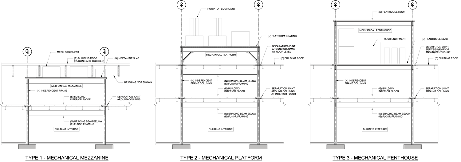
Type 1 is an interior mezzanine, the simplest version of a structurally independent frame. The columns typically go through any interior building floor(s) but do not penetrate the roof. Columns installed through floors require floor openings. A 3-foot by 3-foot opening is typically adequate for most columns and tolerances. After installing the columns, infill the openings with matching floor construction, but provide proper separation joints for fire separation between floors and relative movement between the original and new structure. Ideal candidates for this system type are tall warehouse structures with lightly framed roofs, buildings with shallow purlins with widely-spaced deep roof trusses allowing equipment and access between the trusses, or buildings requiring intermediate floor space for mechanical or other occupancy uses.
Type 2 can be used if the existing building has limited overhead clearance for a mezzanine or a lightly framed roof structure that cannot support the new equipment. In this system, the independent platform frame extends through the roof. Sometimes, designers add screens to conceal the rooftop equipment; however, the screens can add significant wind load to the building. The engineer and the architect must pay close attention to the details of columns penetrating the roof to provide adequate movement, maintain fire separation, prevent leakage, and minimize thermal bridging. The size of the roof openings is similar to the floor openings of Type 1. The Type 2 system typically works well with existing 1-2 story buildings. For taller buildings, the column sizes can be large and uneconomical due to long unbraced lengths and lateral load stiffness demands, and larger columns increase the likelihood of interferences with intermediate existing structures and MEP-FP service lines at lower floors.
Type 3 is an independent exterior penthouse. This system is similar to Type 1, except exterior, and Type 2, except enclosed. The authors consider this system when the renovation requires additional indoor mechanical units, but there is insufficient interior space or height clearance.
Design Considerations Common to All Types
Common design considerations exist for all independent equipment frame types described in the previous section.
Lateral Load Resisting System (LLRS)
Like buildings, independent equipment frames require their own LLRS and close coordination with the project team and stakeholders to select the best system and layout. The authors have used braced frame and moment frame systems. The authors found that architects and owners typically opt for moment frames because they introduce less structure into the interior spaces where the owner or end-users are accustomed to only the existing structure. Although moment frames have less interior structure than braced frames, moment frames usually require deeper beams.
For seismic loads, the designer must determine whether the independent equipment frame is a “building structure,” “nonbuilding structure,” or “nonbuilding structure similar to a building,” as defined by ASCE 7, to select the appropriate design method. The authors believe that most independent frames should comply with the seismic design requirements for a “building structure” (ASCE 7-16 Ch. 12) so that the frame has performance and reliability similar to or exceeding those of the surrounding building.
For wind loads, the authors consider shielding provided by the surrounding building; therefore, the Type 1 system is not subject to wind loading. The Type 2 system is subject to the loads defined by ASCE 7-16, Chapter 29 (Building Appurtenances). Depending on the footprint of the Type 3 system, ASCE 7-16 Chapter 29 applies for penthouses with a small footprint relative to the building, or Chapter 27 or 28 (Building Structures) applies for penthouses with large footprints compared to the main building. The design wind pressures will be higher for penthouses with a small relative footprint.
The independent equipment frames often require intermediate beams below the floor and roof levels. These beams serve two primary purposes: 1) brace multi-story columns and 2) being part of the LLRS. These beams should be set sufficiently below the existing floor or roof structure to accommodate deflection and construction tolerances of the new and existing structures. The engineer must coordinate these beams with the project team because they reduce overhead clearance and may clash with existing or proposed MEP-FP service lines.
Column Layout and Foundations
Locating new columns and footings within the existing structure is a multivariable challenge. The column layout must avoid existing roof and floor framing and provide sufficient clearance for the relative movement of the two structures and construction tolerances.
Foundation exploration via selective demolition or test pits should be performed early in design to locate and understand all below-grade elements. For the equipment frame foundations, designers should consider proximity to existing foundations and other below-grade obstructions, like under-slab utilities.
Separation joints between existing and new foundations are unnecessary since the relative horizontal movements at the foundation level are generally negligible. However, where the new and existing foundations abut, provide a bond breaker between the foundations to reduce unintended gravity load transfer.
Designers should avoid retrofitting the existing foundation for the new frame column with large gravity loads to create a combined foundation because there could be differential settlement when loading the new column.
For buildings supported on shallow foundations, the authors consult with the geotechnical engineer and typically design the new foundations for an allowable bearing pressure less than the original design bearing pressure to reduce the risk of excessive differential settlement.
The equipment frames require new piles and pile caps for buildings supported on deep foundations. Drilled-in piles are typically used to control vibration and noise transmission. The existing structural slab must be locally removed and replaced for the new deep foundation installation. The slab replacement must be isolated from the new columns.
Installing new foundations in buildings where the base slab resists sustained hydrostatic uplift pressures (i.e., pressure slabs) is likely technically infeasible or not economically practical.
It is usually preferable to place the new frame columns as close to the existing building columns and exterior walls as possible to maximize program flexibility. These schemes often result in foundations with eccentric loadings. The authors regularly use strap beams to resist eccentric foundation loads.
Separation Joints
The interfaces between the new frame and the existing structure require separation joints to isolate the new frame properly. Figure 2 shows a Type 2 structure with columns penetrating the existing roof deck with separation joints. The joints must accommodate the relative lateral movement between the new and existing structures (i.e., the two structures moving towards or away from each other) and incorporate fire protection requirements.
To estimate the existing building’s horizontal movement, designers commonly use the IBC and ASCE 7 maximum drift limits to estimate the wind and seismic movements of the existing building instead of analyzing the entire building.
The structural engineer must provide the selected joint size to the architect and other project team members. Designers must detail the architectural and MEP-FP elements that cross the joints to accommodate the relative movement. The design team must clearly indicate these requirements in the contract documents. During construction, the structural engineer should inspect the as-built separation joint to ensure the new and existing structures are not inadvertently tied together.
Fire Protection
Fire protection requirements can impact the structural and separation joint detailing and must be coordinated with the project’s architect and code consultant.
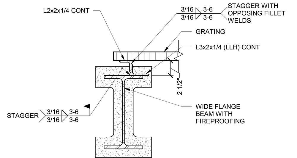
In one instance, there was a need for continuous fireproofing around beams that support grating for equipment access. The grating would have conflicted with the fireproofing. The authors raised the grating above the fireproofing using continuous angle bolsters like those in Figure 3 to allow for continuous fireproofing.
The architectural or code drawings should clearly delineate the extent of fire protection to avoid unnecessary fireproofing. Depending on the project, the new frame may not require fire protection compared to the adjacent existing construction.
Type 2 and 3 Specific Design Considerations
Type 2 structures have interior and exterior structural elements. Since the columns pass through the roofing, they can create a thermal bridge. Designers can provide a thermal break at the roof’s insulation plane, consisting of a thermal isolation pad, module, or coating. The architect, envelope consultant, and mechanical engineer should review the impacts of this bridge and determine whether they should provide a thermal break.
Where the frames are located in buildings with considerable floor-to-floor heights, such as warehouses, it is possible to infill with intermediate framing, similar to the Type 1 system, to create an interior mezzanine space. Depending on the project, the owner may want flexibility to add the infill floors in the future; therefore, designers should discuss the current and future conditions with project stakeholders to determine design requirements.
A significant design consideration for Type 3 structures is the penthouse height. Avoid setting the penthouse floor at or below the roof elevation to improve waterproofing and reduce leakage potential. To minimize the penthouse height, the designers can set the floor slightly above the adjacent roof elevation, approximately 6 inches. If a higher penthouse elevation is acceptable, the designers can locate the mechanical level above the existing roof, creating an interstitial space. In that case, most of the roof structure can remain, except for small roof openings to install the columns like Type 2. Depending on the project, the interstitial space may present some challenges if it requires conditioning, fireproofing, and accessibility for maintenance.
Since the Type 3 system may create a large opening in the roof diaphragm, the diaphragm stresses near the opening can be significant and may require local diaphragm strengthening. Also, the penthouse may change the wind uplift zones on the existing roof; therefore, the engineer should check the deck fasteners for combined in-plane shear and uplift loading.
Snow drifts could accumulate next to the new frame depending on the proximity of the Type 2 and 3 systems to the roofing. Starting with ASCE 7-16, Section 7.8 specifies that drift loads may be ignored when the bottom of the platform or other projection is at least 2 feet above the balanced snow load height. The engineer must evaluate the existing structure, including the roof deck, beams, columns, and their connections, to confirm adequacy for any added snow loads.
In addition to snow drifts, designers should consider potential reroofing when establishing the clear height under the platform in a Type 2 structure. The National Roofing Contractors Association (NRCA) Roofing Manual for Membrane Roof Systems contains recommendations for clearances under the platform to allow for roofing.
Conclusion
For projects that add significant gravity and lateral loads to existing buildings, new independent frames within an existing building can reduce the impacts on the existing building’s structure. A successful design of these independent frames relies on proper detailing and close coordination with the project team during design and construction. ■
Kyle A. Karschner, P.E., S.E., is a Senior Consulting Engineer at Simpson Gumpertz & Heger’s office located in Waltham, MA (kakarschner@sgh.com)
Jacob Sun, P.E., is a Consulting Engineer at Simpson Gumpertz & Heger’s office located in Waltham, MA (jsun@sgh.com)
Michael F. Hughes, P.E., S.E., is an Associate Principal at Simpson Gumpertz & Heger’s office located in Waltham, MA (mfhughes@sgh.com)