
Let’s review TMS 402/602 for answers.
What is the maximum spacing of vertical reinforcement in masonry walls? Without additional information, the answer is typically quite simple: The Building Code Requirements and Specification for Masonry Structures (TMS 402/602)does not specifically include a maximum spacing for either horizontal or vertical reinforcement in masonry walls other than what is required based on structural demand or what is required to meet minimum seismic design requirements.
As we work through the TMS 402/602, we find a maximum effective compression width for each reinforcing bar in Chapter 5, which deals with Structural Members, that will factor into the vertical reinforcement spacing. In Chapter 7, which addresses Seismic Design Requirements, we find that there are prescriptive reinforcement requirements for participating elements that include limits on the vertical and horizontal reinforcement spacing based on the Seismic Design Category (SDC) of the structure. In Chapter 9, which focuses on the Strength Design of Masonry, we also have limits on material properties (including reinforcement strengths) and deflection, as well as ductility requirements that affect the required reinforcement spacing. The International Building Code (IBC) does not include any more restrictive requirements than those found in the TMS 402/602 as it relates to the maximum vertical reinforcement spacing in masonry walls.
Especially for structures in low SDCs, our recommendation for the most economical wall assembly is to utilize a moderately sized reinforcement bar at the widest possible spacing. We have found that this assembly has not only been the most economical in terms of cost, but it has also significantly reduced construction schedules.
Effective Compression Width
The genesis of many of the questions relating to the maximum spacing of reinforcement in masonry walls can be found in Section 5.1.2, which addresses the Effective Compression Width. For simplicity, this article will focus on masonry laid in running bond, which is the placement of masonry units such that the head joints in successive courses are horizontally offset at least one-quarter of the unit length1. For masonry laid in running bond, Section 5.1.2 states that the width of the compression area used to calculate member capacity shall not exceed the least of:
- Center-to-center spacing of the reinforcement.
- Six multiplied by the nominal wall thickness.
- 72 in.
Based on this requirement, many engineers often limit vertical reinforcement spacing in 8-inch CMU to 48 in. on center since this is equal to six multiplied by the nominal wall thickness (e.g., 8-inch.). However, limiting the vertical reinforcement spacing to the maximum width of the compression area would ignore the fact that portions of the wall can span horizontally between the reinforced sections and would thus be an unnecessarily conservative assumption.
Prescriptive Seismic Requirements
The TMS 402 requires that masonry elements be classified in accordance with Sections 7.3.1 and 7.3.2 as either participating or nonparticipating elements of the seismic-force-resisting system. For simplicity, this article will focus on participating elements, including masonry walls that are part of the seismic-force-resisting-system, and specifically on Ordinary Reinforced Masonry Shear Walls (ORMSW) and Intermediate Reinforced Masonry Shear Walls (IRMSW).
Table CC-7.3.2-1 of the TMS 402 includes requirements for masonry shear walls based on shear wall designation, and an abbreviated version is included below in Table 1:
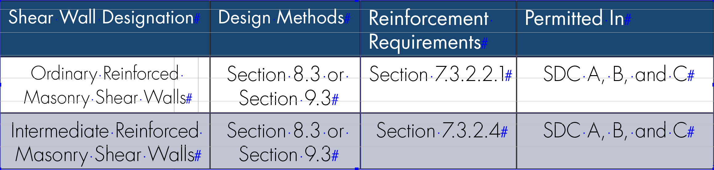
The Minimum Design Loads for Buildings and Other Structures (ASCE/SEI 7) includes design coefficients and factors for seismic-force-resisting systems in Table 12.2-1. As shown in Table 12.2-1, ORMSW construction is permitted in SDC A, B, and C with a maximum structural height of 160 ft. in SDC C. IRMSW construction is permitted in SDC A, B, and C with no limitations on structural height.
Starting with ORMSW construction, the minimum reinforcement requirements are provided in TMS 402 Section 7.3.2.2.1 and summarized below:
Vertical reinforcement of at least 0.2 in.2 in cross-sectional area shall be provided at corners, within 16 in. of each side of openings, within 8 in. of each side of movement joints, within 8 in. of the ends of walls, and at a maximum spacing of 120 in. on center.
Horizontal reinforcement shall consist of at least two longitudinal wires of W1.7 joint reinforcement spaced not more than 16 in. on center, or at least 0.2 in.2 in cross-sectional area of bond beam reinforcement spaced not more than 120 in. on center. Horizontal reinforcement shall also be provided: at the bottom and top of wall openings and extend at least 24 in. but not less than 40 reinforcement bar diameters past the opening; continuously at structurally connected roof and floor levels; and within 16 in. of the top of walls.
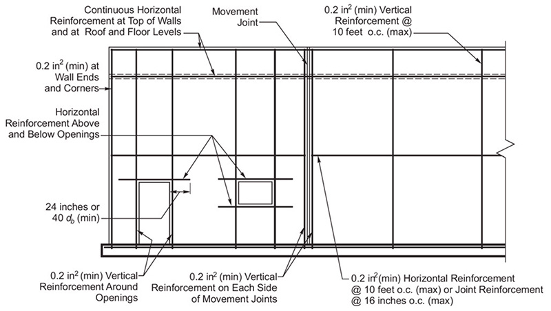
Thus, for ORMSW construction, the maximum vertical reinforcement spacing is limited to 120 in. on the center, which exceeds the maximum width of the compression area specified in TMS 402 Section 5.1.2. The minimum prescriptive reinforcement requirements for ORMSW construction are shown in the 2015 Design of Reinforced Masonry Structures, which has been copied above in Figure 1.
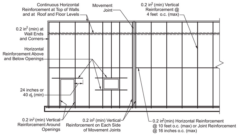
For IRMSW construction, the minimum prescriptive reinforcement requirements are the same as that of ORMSW construction except that vertical reinforcement spacing shall not exceed 48 in. as noted in TMS 402 Section 7.3.2.4. The minimum prescriptive reinforcement requirements for IRMSW construction are shown in the 2015 Design of Reinforced Masonry Structures, which has been copied above in Figure 2.
Based on this information, it is reasonable to assume a practical maximum vertical reinforcement spacing of 120 in. on center. It is also worth noting that for nonparticipating elements, which are not part of the seismic-force-resisting system, there are not any prescriptive reinforcement requirements. However, the 120 in. is a reasonable limit.
Structural Demand
Let’s look at an example of a non-bearing 15 ft. 4 in. exterior masonry wall constructed with 8-inch units. We can calculate the required vertical reinforcement spacing to meet the structural demand assuming a strength level design wind pressure of 27.50 psf.
As a first estimate, we can assume that the wall does not have any axial load applied and, thus, is resisting a purely flexural load. We will also assume the following:
- Effective Depth (d) = 7.625 in./2 = 3.8125 in. for a centered reinforcement bar
- Strength Reduction Factor (𝜙) = 0.90 for reinforced masonry in flexure and axial
- Effective Width (b) = 12 in.
- Specified Net Area Compressive Strength of Masonry (f’m) = 2000 psi
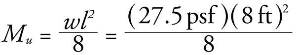
Step 1: Calculate design moment (Mu)
Using Strength Design, the controlling load combination for out-of-plane design is typically 0.9D + 1.0W in low seismic areas.
Thus, the design moment (Mu) can be calculated as follows:
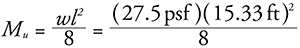

Step 2: Calculate the equivalent stress block (a) and verify that it is located within the face shell of the unit.
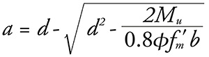
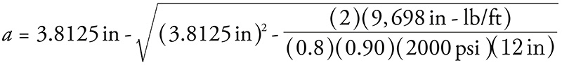
a=0.150 in
The minimum face shell thickness specified in ASTM C90 is 1.25 in. for nominal widths greater than 8-in. Thus, since the equivalent stress block is less than the face shell thickness, the unit can be designed as a rectangular section.
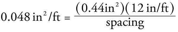
Step 3: Solve for the required area of steel (As,req).
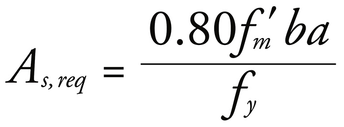
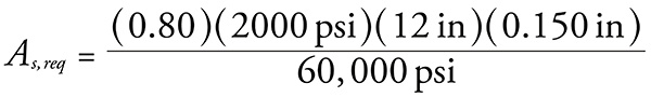
As,req=0.048 in2/ft
Step 4: Select a reinforcement spacing.
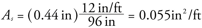
The area of a #6 vertical reinforcement bar (As,bar) is 0.44 in2. Since the required reinforcement area for flexure is 0.048 in2/ft, we can solve for the nearest modular spacing.
Thus, the required spacing is 110 in. We will assume a spacing of 96 in. on center since this is greater than the effective compressive width per bar and will affect the capacity. The actual reinforcement provided can then be solved:
Step 5: Solve for the effective compression width per bar.
As stated in TMS 402 Section 5.2.1, the effective compression width per bar is the minimum of the center-to-center bar spacing, six multiplied by the nominal wall thickness, and 72 in. Thus, for our case, the effective compression width per bar would be the minimum of 96 in., 48 in. [(6)(8-in)], or 72 in., where 48 in. will control.
Step 6: Verify capacity.
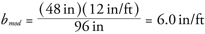
Since the reinforcement spacing is greater than the effective compression width per bar, we must verify that we have sufficient capacity. The simplest way to accomplish this is by factoring down the unit width (b) to account for the larger spacing.
Now we can solve for the modified factored moment capacity (𝜙Mn) and compare it to the design moment (Mu).
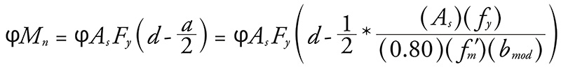

φMn=10,813 in‒lb/ft
Thus, since the factored moment capacity (10,813 in‒lb/ft) is greater than the design moment (9,698 in‒lb/ft), the reinforced masonry wall has sufficient capacity.
Step 7: Create an interaction diagram.
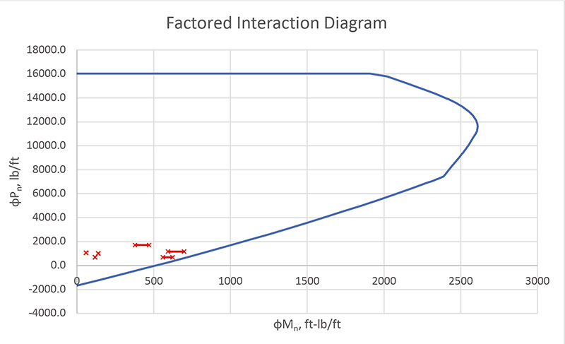
Solving flexural behavior is a good estimate of the required reinforcement. However, to verify that the wall has sufficient capacity, an interaction diagram is required to verify that the wall can resist all combinations of axial and flexural loads. A sample interaction diagram is provided below in Figure 3 for this wall. It shows that for all load combinations, including second-order effects, the 15’-4” wall has the sufficient capacity with (1) #6 vertical reinforcement bar at 96” on center. For the purposes of this interaction diagram, a 500 lb/ft dead load and 500 lb/ft snow load were added to the wall. The second-order deflection was calculated to be 0.09 in., which is less than the deflection limit of 1.3 in.
Discussion
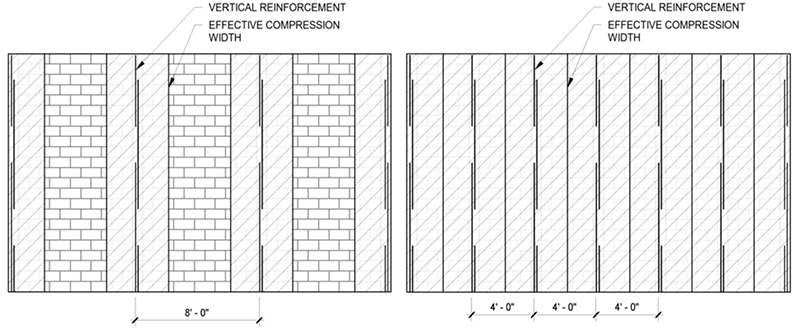
If we place movement joints at 24 ft. 8 in. on center for crack control and we evaluate the impact on a wall panel comparing a spacing of 48 in. on center to our calculated spacing of 96 in. on center, we will have reduced the spacing from six (6) equal spaces to (3) equal spaces as shown in Figure 4 below. This reduction equals a significant decrease in terms of required grout and reinforcement:
A 53% reduction in grout volume. For a spacing of 48 in. on center, 0.23 yd3 would be required per 100 ft2 of wall area versus 0.11 yd3 for a spacing of 96 in. on center. NCMA TEK 09-04Awas used to estimate grout volumes.
A 43% reduction in reinforcement weight. Assuming low lift grouting (limiting grout lifts to 5 ft. 4 in.) and lap lengths, 170 ft. 4 in. of reinforcement would be required for every wall panel with a spacing of 48 in. on center versus 97 ft. 4 in for a spacing of 96 in. on center.
Based on several Michigan contractors interviewed for this article, the increased spacing will result in an approximately 7% reduction in the wall square foot cost. The reduction in cost for other regions, states, and markets would need to be evaluated.
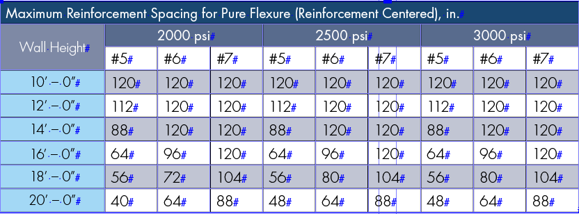
The specified net area compressive strength of the masonry (f’m) will typically not significantly impact on the spacing of reinforcement for walls acting predominantly in flexure. If we compare the factored moment capacity of the example wall in pure flexure (10,813 in‒lb/ft) versus the same wall with an f’m equal to 4000 psi, we find that we only realize a 2.3% increase in factored moment capacity. Thus, although f’m has a major impact in other areas, it has a relatively minor impact on flexure compared to reinforcement size and spacing for walls with low axial load. For various partially grouted wall heights and a 30 psf wind load, the maximum reinforcement spacings are shown below in Table 2. The wall was assumed to have no axial load applied.
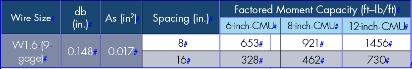
What about the horizontally spanning section of the wall between the vertically reinforced sections? The simplest method is to use horizontal joint reinforcement already present for crack control to distribute the lateral load horizontally into the vertically reinforced strips. For flexural tension parallel to bed joints (horizontally spanning masonry), TMS 402 Section 9.1.9.3.2 permits joint reinforcement to be used as primary flexural reinforcement. The typical yield strength of joint reinforcement is 70,000 psi. Strength Design of Masonrydiscusses this procedure, and an excerpt from this publication has been copied below in Table 3 to present the design moment capacity from joint reinforcement:
For example, if we have a wind pressure of 27.5 psf and have a vertical reinforcement spacing of 120 in., we can conservatively assume a simple span condition with the span length equal to the reinforcement spacing. In some cases, we may be able to consider a continuous span depending on support conditions. We can then calculate the design moment:
Mu=220 ft‒lb/ft
With W1.7 (9 gages) horizontal joint reinforcement at 16 in. on center, we have a factored moment capacity of 462 ft-lb/ft, which is greater than the design moment. Further addressing horizontally spanning masonry, the National Concrete Masonry Association (NCMA) Foundation funded research and a report by W. Mark McGinley, including testing at North Carolina A & T. The final report found that for masonry walls with reinforcement at a wide spacing, a shallow arch formed which could transfer significant loads between vertically reinforced sections. The final report is available through the NCMA.
This article discussed approaches to design CMU walls for flexure based on the TMS 402 requirements rather than limiting reinforcement spacing to 48 in. or six multiplied by the nominal wall thickness. Especially for walls in low SDCs where ORMSW and IRMSW are permitted, the most economical masonry walls use moderately sized reinforcement bars at the widest possible spacing.■
References
(2016). Building Code Requirements and Specification for Masonry Structures. Denver, CO: The Masonry Society.
(2016). Minimum Design Loads for Buildings and Other Structures. Reston, VA: American Society of Civil Engineers.
(2015). 2015 Design of Reinforced Masonry Structures. Citrus Heights, CA: Concrete Masonry Association of California and Nevada.
Grout for Concrete Masonry, TEK 09-04A. Reston, VA: National Concrete Masonry Association.
(2016). Standard Specification for Loadbearing Concrete Masonry Units. West Conshohocken, PA: ASTM International.
(2020). Strength Design of Masonry. Denver, CO: The Masonry Society.
(2007). Spacing of Reinforcing Bars in Partially Grouted Masonry. Reston, VA: NCMA Education and Research Foundation.