
Incorporating Perforated Brickwork into Anchored Brick Veneer.
Perforated brickwork or brick masonry screen walls have a long history of use worldwide. The earliest known examples are found in Persia and the Middle East. More contemporary examples can be found in India. In hot climates like these, perforated brickwork helped screen the sun while allowing light and air to filter into the space beyond. Other names include pierced walls, lattice walls, hit-and-miss brickwork, and jali. For consistency in this article, the term “perforated brickwork” will be used.
Perforated brickwork in the United States has typically been used in landscape applications such as garden walls or small utility enclosures, where their design and construction were empirical. More recently, the Brick Industry Association (BIA) has received inquiries requesting guidance for incorporating perforated brickwork into building facades at a larger scale. Inquiries generally include an inspirational photo without detailed information about the source project, which is typically located outside the United States.
The industry does not have a formal guide or comprehensive resource for the design and analysis of perforated brick walls/screen walls at this time. Still, it has compiled several resources and recommendations that are provided in response to the inquiries.
This article intends to present these resources to a broader audience while the industry is working to develop guides and references to catch up to the increased popularity and expanded use of perforated brick masonry.
Design
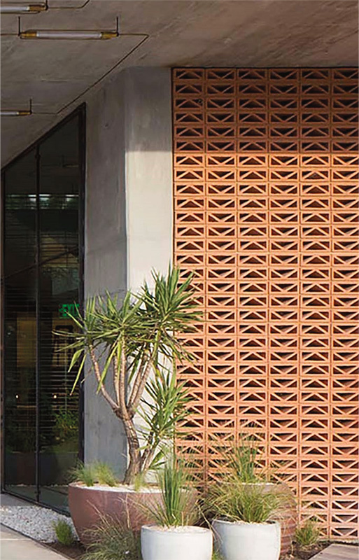
Methodology. The desired screen pattern dictates the design approach. Some screen patterns, such as that shown in Figure 1, utilize a clay solar screen tile, sometimes referred to as a “breeze block,” which is a hollow-fired clay unit with decorative perforations through the exposed face. These units typically maintain a solid rectangular or square perimeter. This solid perimeter and unit format allow them to be laid like traditional masonry, in accordance with the prescriptive code requirements for veneer, because there are full head joints between units and continuous bed joints. Per the prescriptive code requirements, if units are laid in a configuration other than running bond, such as that shown in Figure 1, veneer wire reinforcing with a minimum size of one W1.7 wire is required to be placed in the bed joint mortar at a maximum of 18 inches on center vertically.
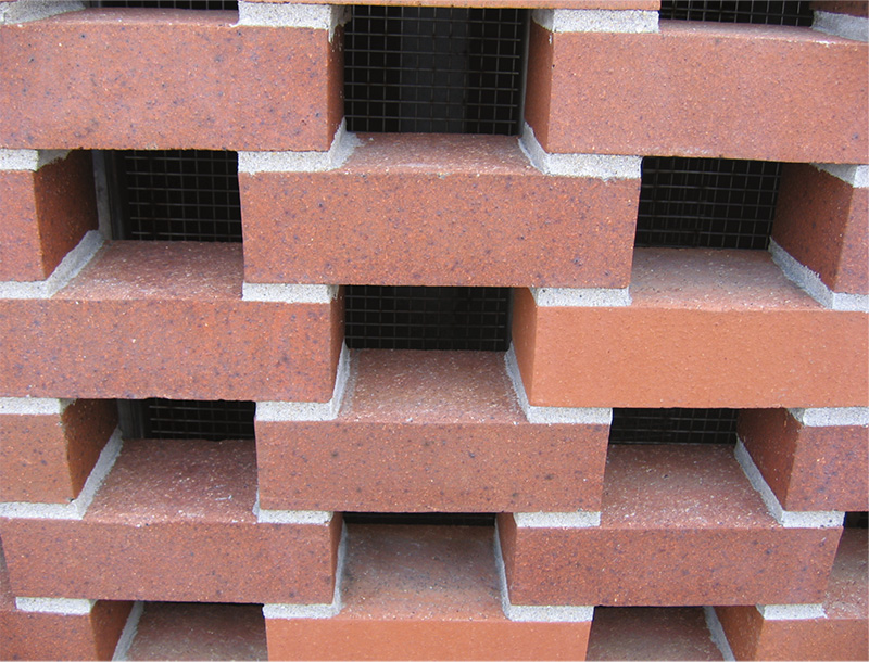
Other screen patterns incorporate solid clay brick units laid such that there are gaps in place of head joints to create the perforations (Figure 2). The lack of head joints change the veneer’s behavior, so the masonry code’s prescriptive provisions, TMS 402 – Building Code Requirements for Masonry Structures (TMS 402), no longer apply. In such a case, the alternative design provisions in the veneer chapter of TMS 402 are used as a substitute compliance path. These alternative design provisions consist of an engineered rational design method that applies the following four requirements or guidelines:
- Loads shall be distributed through the veneer to anchors (as applicable), and the backing through the principles of engineering mechanics
- Veneer stability must be maintained through limits to out-of-plane deflection
- The veneer need not be subject to the flexural tensile strength provisions of the Allowable Stress Design and Strength Design chapters in TMS 402.
- The general requirements for veneer must be met, along with the criteria for veneer not laid in running bond and the seismic prescriptive provisions.
Note that the 2022 version of TMS 402 includes a new engineered design method referred to as the “Tributary Area Method.” This method should not be applied to the design and analysis of perforated brickwork, as the analyses performed to develop the method assumed masonry with head joints.
Wind Load. While calculating components and cladding wind loads is relatively straightforward, applying these loads to the perforated brickwork is less so. The presence of the perforations suggests that the loads should be reduced to reflect the proportion of the solid area. However, each unit within the screen pattern will have exposed top and side surfaces that experience drag and suction, resulting in a net wind load that is larger than expected by the proportion of solid area alone. Using unmodified components and cladding wind loads calculated for non-perforated claddings is recommended.
Existing Resources. The obsolete BIA Technical Notes on Brick and Tile Construction publication “Clay Masonry Shading Devices,” dated March 1957, includes some relevant information on the design of perforated masonry, including a formula to estimate the allowable unreinforced span length of a wall in feet.
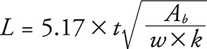
Where:
L = the allowable distance between lateral support in feet
t = the specified wall thickness in inches
Ab = ratio of actual bed joint length in a horizontal plane to the total wall length
k = ratio of solid wall area to total wall area in a vertical plane
w = design wind pressure in pounds per square foot
This formula is based on a standard allowable flexural stress equation (σ = M/S) with coefficients to reduce the section modulus of the wall. It includes an assumption for allowable flexural tension stress of 20psi. Note that the formula includes the old 1/3 stress increase that is no longer permitted.
There has been limited research on the structural behavior and capacity of perforated brickwork, but two relatively recent studies provide insight. Ortlepp and Schmidt tested small-scale specimens in compression and a larger specimen in shear to evaluate their load-bearing capacity. They found the compressive strength of a single wythe solid wall to be approximately 10 percent greater than a single wythe perforated wall. The perforated wall could only carry half of the in-plane lateral force compared to the solid wall. Finite element models demonstrated that the individual units are subjected to bending stresses due to the combination of compressive loading at adjacent units’ bearing points and the unit’s unloaded center. In-plane loads are managed by struts and ties formed through the unit intersections. Out-of-plane loads are managed through shear rotation within each segment of bed joint mortar.
Masia et al.conducted experimental testing of unreinforced perforated brick panels loaded out-of-plane to evaluate both vertical and horizontal bending capacity and to compare with predicted capacities based on tested material strengths and current code equations per Australian Standard AS3700: Masonry Structures. Failures in both bending directions were non-ductile, but the specimens in horizontal bending exhibited larger capacities than predicted. Capacities in the horizontal bending direction were greater than the capacities in the vertical bending direction due to the differences in the loading of the mortar joints. In vertical bending, the out-of-plane load is resisted by the flexural strength of the mortar bed joints, whereas in horizontal bending, the out-of-plane load is resisted by the shear strength of the mortar bed joints and the flexural strength of the units.
Detailing
Reinforcing. Because the unreinforced capacity of perforated brickwork is limited, reinforcing must be integrated into the system. In some cases, this reinforcing is not readily apparent.
Visible support framing is an obvious solution, typically used where the exposed framing would not be aesthetically objectionable. Where having visible support framing is objectionable, such as where the perforated brickwork spans across window openings, the support framing can be camouflaged. For instance, the London School of Economics Student Center used steel framing members fabricated to match both the size of the vertical window mullions and the overlap distance of the brick. Placed at each vertical mullion in the window system, this steel framing created intermediate locations to anchor veneer ties, reducing the unreinforced span length of the perforated brickwork while maintaining the desired appearance from the interior.
Internal reinforcement is necessary in cases where external support framing is not an option. If there are areas of solid brickwork directly adjacent to the perforated sections, these are ideal locations for placing reinforcement, which can consist of a bar or wire. Bed joint reinforcing may also be an option if the solid brickwork is oriented horizontally. Within the perforated brickwork, vertical reinforcing can only be placed within the overlap zones. For some designs, the geometry permits the brick cores to be used for reinforcing. Still, in others, the overlap zone needs to be narrower, and holes must be drilled into units without cores or frogs to incorporate reinforcing. Some of these configurations may not match the assumptions of the reinforced masonry requirements in TMS 402 and will need to be evaluated rationally. Load testing of a full-size mock-up panel would be prudent to help evaluate the design for structural performance.
Durability. Unlike traditional brick masonry veneer, the perforated brickwork openings expose the brick units’ multiple sides to the environment and allow water to accumulate on horizontal surfaces. Because of this increased exposure inherent to the system, the performance of the perforated veneer walls will be different from that of traditional brick masonry veneers. The risk of general deterioration and freeze-thaw damage is higher.
It is recommended to use solid brick without cores or frogs. Standard solid brick units conforming to ASTM C216 – Standard Specification for Facing Brick (Solid Masonry Units Made from Clay or Shale) are permitted to have up to 25% cores, so units without cores or frogs must be explicitly specified. Use of cored units in perforated brickwork has been successful, but generally in more southern climates, where the risk of freeze-thaw is low. ASTM C902 – Standard Specification for Pedestrian and Light Traffic Paving Brick has minimum requirements for strength and cold water absorption that exceed those required for units meeting ASTM C216 Grade SW due to their use in horizontal applications. Selecting bricks that meet these more stringent requirements can provide additional durability in the more severe exposure of perforated brickwork.
If special-shaped units are feasible on the project, consider units with sloped top surfaces and drip grooves at the underside to reduce the potential for ponding water on the horizontal surfaces. Some manufacturers sell special-shaped units with oversized cores at the unit ends for reinforcing but uncored in the center. Special-shaped units can also be used in the adjacent solid sections to create internal space for reinforcing and grout while maintaining the appearance of the exterior.
With respect to other considerations to increase durability, polymer-modified mortar is an option to improve the durability of the mortar, but be aware that its use requires more care because of the difficulty of removing polymer-modified mortar smears from brick faces. Consider specifying stainless steel for veneer ties and horizontal joint reinforcement instead of galvanized steel. If desired, a post-applied breathable water repellent can be considered.
Closing
Perforated brickwork has a long history of successful use in many countries worldwide; however, the incorporation of perforated brickwork into anchored brick veneer is a relatively new variation of this concept.
As the masonry industry continues to develop formal guidance on the design of perforated brick veneer, the alternative design provisions in the code allow engineers the latitude to achieve the design intent. The information presented here can provide some guidance to engineers in the meantime.■
References
Ortlepp, S. and Schmidt, F., “Perforated Masonry – Lightweight Construction,” Ninth International Masonry Conference, Guimarães, Portugal, 2014.
Masia, M., Simunic, G., and Page, A., “Flexural Strength of Unreinforced Lattice Masonry Walls Subjected to Lateral Out-of-Plane Loading,” 13th Canadian Masonry Symposium, Halifax, Canada, 2017.