
Thoroughbreds, donkeys, & dead horses.
“The Importance of Building Information Modeling (BIM) in Structural Engineering” was the title of a 2008 October article in this magazine that stated, ‘In varying ways, in less than ten years, BIM will permanently change the structural engineering profession and its universities, firms, clients, markets, design codes, digital tools, contracts, insurance policies, global recruitment of staff, work process, and many other aspects.’’
The readers may judge the merit of that past 2008 article. Today, this article in 2023 looks forward with the belief that the Structural Engineering (SE) profession, and concrete BIM, specifically, will see more changes over the next seven years leading up to 2030 than seen in the previous three decades. Fortune will favor Structural Engineers with a vision to see the trends in concrete and technology.
Past Three Decades
The ’90s saw the early concepts of low-resolution 3D modeling emerge in concrete even though much of the SE process was still analog. The field still used pencils to work out formwork on the structural drawings. SE firms produced the Contract Documents (CD) as a shaken but not stirred cocktail of base Computer-Aided Design (CAD) work, sticky back details, and notes with a little hand lettering/linework sprinkled throughout for spice. Simply printing a set of CDs could take a full day on the plotters. By the end of the decade, most of the CDs were pure single malt CAD produced for the initial Issued For Construction (IFC) set but quickly turned into the good ‘old fashion’ cocktail with hand sketches and notes in the record set as Requests For Information (RFIs) and addendums were mixed in during construction. None of the ‘as-builts’ were ever served ‘neat’ to the owner and often looked like they were on the rocks for a while and a little watered down in the information gathering between the field and office. Young engineers of the time will remember that concrete shop drawings sometimes had up to seven copies requiring manual hand transfer of red marks to all the sets with a wet submittal review stamp. These were then rolled up and rushed out to a courier or overnight shipping roll to get the submittal off the clock of the SE’s review logs. RFIs were often answered by intuition, wisdom, and experience by the SE initially over the phone with the GC’s field engineer. The SE would follow this up ‘formally’ with confirming hand calculations that went late into the day. They had to pencil-whip a hand sketch they would then throw in the fax machine to help the GC adjust the final rebar placing before that week’s concrete pour in some cases. The GCs had limited internet at the job trailers, and often the SEs would visit the site when an issue arose. Following site visits, the SEs might take a roll of film to be developed for the photos until digital cameras emerged at the end of the ’90s. Many of the reproduced drawings were still blue line copies with the familiar aroma of ammonia from the diazo printing when they were first unrolled. The concrete design was analog with engineers flipping through their paper copy of ACI 318-95 as they moved through different software applications to address the different concrete elements for floor plans, beam schedules, column schedules, pier schedules, etc. Young SEs of the time will also remember the heated debates among principals as to whether Engineers-In-Training (EITs) should be allowed company email addresses and access to web browsers at their work computers, given the firm’s limited bandwidth on 56k/s dial-up modems. Full 3D models of frames and 3D Finite Element Analysis (FEA) models of complete two-way flat plates with irregular openings were emerging.
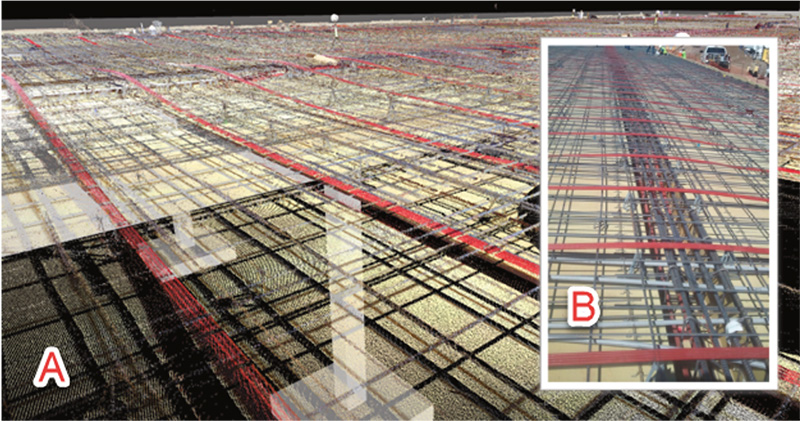
By the mid-2000s, some SEs began issuing their first projects with commercially available structural-focused BIM applications. They could immediately see the limitation in structural BIM applications: computer model size and detail capabilities with concrete. Around the mid-2010s some SEs began seeing robust full 3D rebar models of irregular complex concrete shapes such as hydro-electric dams. These complex rebar models were developed by progressive detailers working at larger rebar fabricators. These advancements of the time were due to rapid growth in computer power, operating systems, and BIM application capabilities to handle larger concrete models. Near the end of the 2010s, the use of cloud-based team models began to expand rapidly, and 4G and 5G networks began taking concrete BIM to the field. In the 2010s, the use of laser scanning of concrete and rebar began to be utilized for field validation and creating as-built PT tendon locations for owners, for example (Figure 1).
The 2010s also saw the emergence of clearly defined areas of BIM in design and construction litigation. Since the early 2010s, the author has been requested by attorneys as an expert on the topic of BIM and Virtual Design & Construction (VDC) in building design and construction litigation cases in the US and Canada on a variety of project types. While this article cannot address specific cases, it does share an SE’s perspective of common trends and lessons learned from BIM litigation with emerging technology. Themes in BIM disputes typically involve miscommunication of the scope, schedule, fee, Level of Development (LOD), and firms’ marketing around BIM.
Even with all the changes noted above, there remains one area of the SE profession that has not consistently advanced with BIM over the last three decades. It is the sociology and attitudes of SE firms and the principals who own those firms that has lagged the technology changes with BIM. Too often, SE firms begrudgingly admit that BIM helps them produce 2D documents. At the same time, they see any further use or innovation of BIM as someone else’s issue and none of their business.
Level of Development (LOD)
LOD has played such a central role in BIM disputes that it should be addressed first. The American Institute of Architects (AIA) has a well-established set of definitions for LOD beginning in 2008 with the AIA E201 document. AIA updated their definitions in 2013 and, most recently, in 2022 with the AIA E202-22 ‘BIM Exhibit for Sharing Models with Project Participants’.
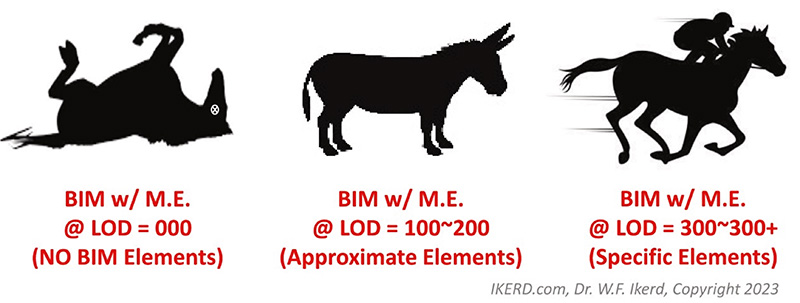
It is understood that LOD may seem tedious, like the ‘excitement’ of reading a dictionary. However, LOD provides the terminology needed in contracts with BIM. LOD is how BIM scope is defined for claims against SE firms for both errors and omissions as well as breach of contract when SEs do not provide what they knowingly (or unknowingly) commit to with BIM in writing. Ignorance of BIM and LOD by SEs has not typically been a good business model or defense when claims are made against them. Moving forward, SEs should consider an informed use of AIA 2022 LOD definitions in their scopes and avoid any home-grown definitions of LOD from their firm or the architects or builders they work with. When considering the Level of Development (LOD) for Model Elements (ME) in BIM, consider a promisor who committed to provide a thoroughbred horse (ME LOD @ 300~300+) to a recipient who placed a bet to complete a race in a given time for a given effort (project bid) before the promisor let them look at the beast. If the promisor then provides a donkey, mule, old crippled horse (ME LOD @ < 300), or even worse, a dead horse (LOD 000) for the recipient to race instead of the recipient’s entitled thoroughbred (ME LOD @ >= 300), then the promisor may be in breach of contract to the recipient. The takeaway is that dead horses (ME LOD = 000) are good for making glue for those working with only 2D paper and are the correct type of horse for only 2D. The donkey, etc. (LOD 100~200) serve a purpose and are better than the dead horse in carrying a burden (BIM process). The thoroughbred (LOD 300~300+) is the most useful in running a race (O/A/C BIM process) for a given schedule and duration, especially if that is what the recipient was promised and entitled to. Finally, don’t contractually promise thoroughbreds (LOD 300~300+) if you are not going to deliver them and know the difference between a thoroughbred and a donkey, etc. (Figure 2)
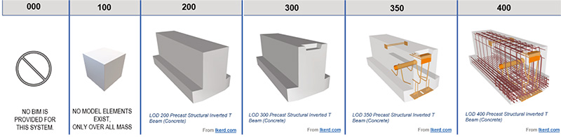
At the risk of beating a dead horse, Figure 3 provides a more concrete example to illustrate the ME progression in BIM from LOD 100 to LOD 400 from the BIMForum Global LOD Specification (bimforum.global). SE firms need to be very comfortable stating that their content is approximately at LOD 200 if that is the case and never state that a whole model is at LOD 300 if they have not verified that all of their objects are in specific locations and can be measured from the model without referring to 2D documentation. LOD 300 is not a trivial loose definition for model elements that means ‘kinda sorta close’ for the SE to wiggle around with. Instead, it is a contractual commitment to an object being specific in terms of (1) quantity, (2) size, (3) shape, (4) location, and (5) orientation within the element’s construction tolerance. If an SE firm does not intend to model an element at LOD 300 (specific), state it as such in the CDs and contract that the element is LOD 200 (approximate).
Regardless of the LOD SEs provide today, the evidence suggests they will be asked to provide higher LOD in the future.
Present Emerging Concrete Technologies
Structures, in general, and concrete, specifically, are expanding their use of many emerging and advancing technologies. Some of these include reality capture laser scanning, drone imaging, thermal data collection during curing, cloud-based multi-stakeholder models, digital 3D shop model reviews of rebar, field data collection from trades and testing agencies on tablets, and the emergence of predictive analytics (PA). The author believes the emergence of predictive analytics, which includes the buzzword of artificial intelligence (AI), will be one of the most remarkable changes coming to the structural engineering profession and concrete industry. For PA and AI to flourish, large data sets are needed. It was only when BIM matured as a relational database over the last decade that such structure for this data was organized. With cloud-based models, PA and AI engines now have the data sets they need for such statistical work. The technology exists for owners, architects, and builders to begin benchmarking quantities and comparative designs for pounds of rebar per cubic yard of concrete. SEs with many simplifying assumptions that result in a little extra rebar will begin to see such solutions transparently illuminated and possibly deemed by O/A/C as overly conservative.
Other emerging concrete innovations are ‘bendable’ ductile concrete, or engineered cementitious composite (ECC) with polymers, Ultra-High-Performance Concrete (UHPC) that adds fibers for greater tension capacity, and many other material advances. These technologies are advancing 3D concrete printing with early structural concrete applications. Research is being done in highly complex 3D voided slab system designs for floors with minimal concrete per square foot of slab. Additionally, the trends for lower carbon footprints on structures will add pressure for more highly optimized concrete systems with more complex geometries. All this effort will partly minimize the material used – not for cost savings but for environmental carbon reduction considerations. Architectural and structural precast will continue to blur as the industry combines them to reduce the overall material, i.e., lower carbon footprint. Other trends in concrete are ‘intelligent equipment’ and the use of robotics in field and precasting operations. Off-site construction demand will increase with a desire for greater use of modular formwork planning that can be automated with detailed 3D structural concrete models. Additionally, other market economic forces may lead to larger concrete contractors with advanced BIM capabilities absorbing smaller non-BIM regional concrete companies through mergers and acquisitions. This consolidation of concrete companies with advanced BIM departments will regionally increase the demand for more advanced concrete BIM earlier in the project in many markets that have not used concrete BIM. These advancements and many others in material and forming technology, along with external environmental and economic forces, will continue to fuel the O/A/C desire and pressure for more developed concrete BIM earlier in projects. SE firms will be asked to do more with less material, with new properties, in more complex, thinner concrete systems requiring greater analysis with designs that are highly integrated with the enclosure of the building than they ever have before by 2030.
In the coming years, a possible sleeping giant in BIM structures will be when building codes, jurisdictions, sureties, bonding companies, insurance carriers, and government agencies such as Occupational Safety and Health Administration (OSHA) begin considering if buildings designed and constructed with higher LOD in BIM have lower risks. SEs will see more BIM requirements with concrete when building permitting begins using BIM with AI to automate code compliance reviews. Scheduling and estimating concrete projects will also see notable advancement and changes in BIM over the next few years, with the rapid emergence of AI being applied to models with elements at higher LOD.
Now What Should SE Firms Consider
For CDs, SEs need to establish key BIM parameters in their general notes and specification: (1) SE’s origin of the model that trade models will reference, (2) what is modeled, (3) what is not modeled, (4) what is the level of reliance on the elements that are modeled, (5) what is expected to be used by the trades in BIM as part of a quality control process that the SE will specify, and (6) what level of model testing for the trade’s concrete BIM will the SE, owner and/or general contractor require before the model is used to create formwork and rebar shop submittals (drawings and/or models). Such testing could include but is not limited to coordination testing and clash detection of concrete systems with other trades’ content as well as phased modeling of pour sequencing, 4D scheduling, and 5D cost estimating.
Several resources are available for SEs to learn more about concrete BIM and what they should consider in their general notes and specifications. Since 2008, the SEI Digital Design (formerly BIM) Committee (SEIbim.org) has maintained BIM resources. Since 2017, Ascend Building Knowledge Foundation (AscendBKF.org/STRUCTURES), a 501c3 non-profit, began focusing on research and training that included work in structures from design to construction. Resources for SE firms are provided at this site with sample general notes, BIM specification language, and sample BIM Execution Plans. In early 2022, the American Concrete Institute (ACI) published ACI PRC-131.3-22, TechNote “BIM Level of Development for CIP Concrete” (ACI BIM LOD 22), which does have some valuable information for SEs to consider, particularly the seven sub-categories of concrete. These categories are (1) Concrete, (2) Reinforcing bar, (3) Specialty reinforcements, (4) Prestressing, (5) Specialty systems, (6) Embedments, and (7) Formwork. However, the ACI document references older AIA LOD 2013 definitions. In late 2022, AIA published its updated LOD definitions, which are the current definitions for new projects that reference them. SE firms should address the ACI BIM LOD TechNote-22’s seven categories of concrete BIM in their contracts, general notes, and specifications and clearly state what LOD they will provide using the AIA 2022 definitions. BIMForum Global (BIMForum.global) has published the 2022 LOD Specification that provides the most current and comprehensive documentation of structural LOD. The BIMForum Global 2023 LOD Specification is scheduled to be published in the fall of this year (BIMForum.Global/LOD).
SEs moving forward will need to be more informed on topics such as reality capture, design automation, AI, and delivering BIM with higher LOD elements as the contract deliverable to communicate design intent. From this informed position, they can better decide what is best for their SE firm’s business. Concrete BIM is a topic that is not going away with the drivers presented in this article. Paraphrasing Heraclitus, “There is nothing permanent except change.” Concrete BIM is not the same today as it was a decade ago, and it will be very different for SEs by 2030.■