
Part Two: Novel and Experimental Design Approaches at the New PDX Terminal
Missed Part One? Read it HERE.
The approximately $2 Billion Portland International Airport Terminal Core Redevelopment Project, located in Portland, OR, is led by the Port of Portland as owner, with a design team featuring ZGF Architects and KPFF as Structural Engineer. It is currently being built by Hoffman-Skanska Joint Venture as CMGC. The project is summarized in Part One, published in the June 2023 Structure, and features many unique structural solutions.. In this article, we will delve deeper into some of the most interesting structural aspects of the project, including design for fire exposure, physical load testing of connections, and the herculean process of erecting the new roof.
Performance-Based Fire Engineering
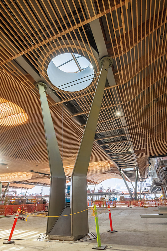
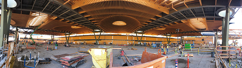
Performance-Based Fire Engineering was performed on the grout-filled architecturally exposed structural steel (AESS) Y-Columns, which feature a cruciform steel core with diagonal steel face plates, forming diamond-shaped cross sections, which taper from a kink point 8’ above the main floor level to the top, roughly 26’ above. Fire scenario analyses were performed by Code Unlimited, which identified a critical design fire for the columns, with time-heat data developed and applied to a thermal heat transfer model to determine the maximum temperatures across the column cross-section at critical locations to ensure that a central steel core within the column can safely support the roof during a fire event. This is possible because the exterior steel face plates are primarily needed for seismic resistance and stability. The grout fill provides an insulating effect and stability for the interior plates, which are adequate to support the roof loads considering elevated temperature effects due to fire. This advanced process allowed the painted AESS columns to be exposed to view above the enplaning level without exterior fire protection materials.
Engineered Lumber and Connections
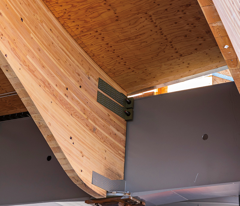
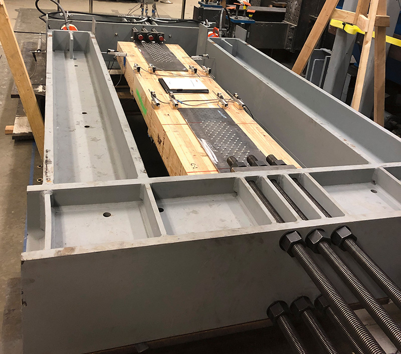
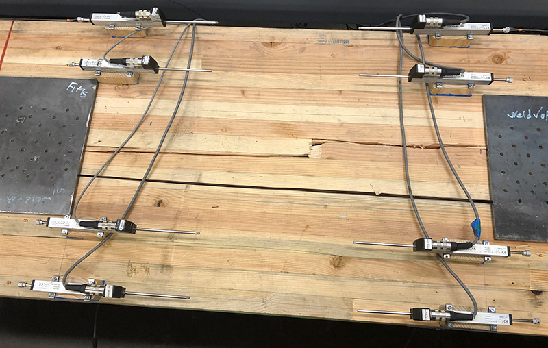
The largest glued-laminted timber (glulam) beams on the project are a prodigious 9’-3” deep occurring at clerestory locations. Wood trade partner, Swinerton Mass Timber (SMT), elected to increase the initially-planned 7’-4 ½” deep glulam beam with curb above into a single massive beam serving as both beam and curb, requiring expanded APA approval, which was successfully achieved. The glulam beams are mostly 6’-4 ½” deep at their ends, where they frame into the steel girders with moment connections for continuity, with a vertical shear and horizontal tension/compression connection at the bottom and a horizontal tension/compression connection at the top of beam designed to accommodate significant vertical shrinkage movement in the glulams. These moment connections allowed for glulam beam cantilevers, provided lateral load transfer between the upper diaphragm level and isolators located below the bottom of the girders, and allowed for optimized continuous beam design for efficiency. The design tension forces in the glulam beam top/bottom connections are significant, up to several hundred kips, requiring the development of project-specific connections, verified through extensive physical load testing in partnership with Portland State University’s structures lab.
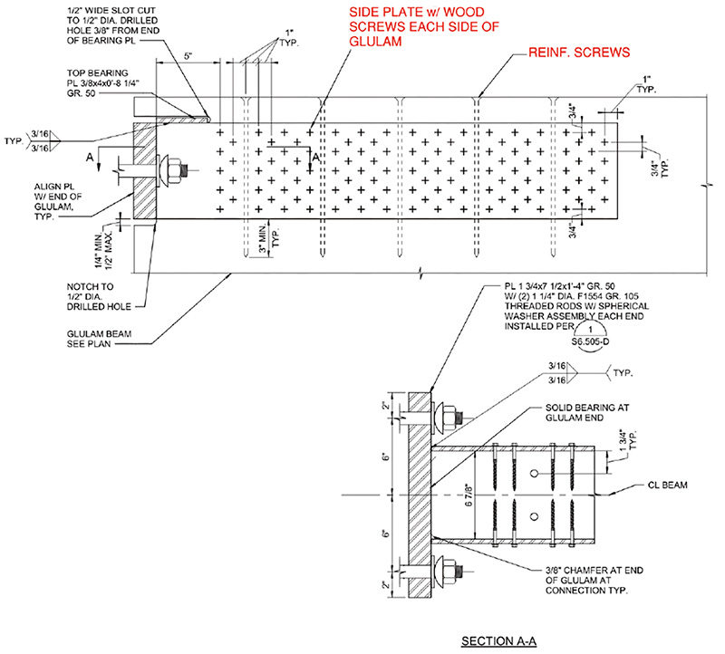
Numerous glulam end connection options were explored, but in partnership with SMT, it was determined that steel side plates with rows of closely-spaced Simpson SDS screws were the most cost-effective solution. Three sizes of connections were developed, a short connection, a long connection, and a double-long connection, with progressively more screws, to cover the wide range of connection demands. The short connections, which have 108 screws distributed between the two sides of the beam, performed well without vertical reinforcing, exhibiting ductile screw bending failures with ultimate tensile strengths of up to 150 kips. The long connections, with 238 total screws, exhibited premature block-shear wood failures when initially tested without perpendicular reinforcing screws, so reinforcing screws were added to subsequent tests to develop ultimate tensile strengths of up to 380 kips and incorporated into the final design. The double-long connections include a total of 476 screws with perpendicular reinforcing screws and achieved ultimate tension test loading of up to 780 kips, a massive load for a screwed connection to wood.
LRFD design methods per NDS were utilized for the roof, with nominal connection capacities developed by ASTM D2915-17 based on the mean ultimate test strength minus a set number of standard deviations based on the sample size of each connection size. Appropriate phi and lambda values were then applied to the nominal capacity and compared to factored design loads to confirm the adequacy of the connections. Load-displacement data from testing showed that connection elongation at service level loading was minimal at under 1/16”, contributing to less than ¼” of roof edge deflection when installed snug tight, which was considered in roof edge elevation cambering.
The large glulam beams posed several additional challenges in this hybrid roof structure. The curved geometry of the beams causes cross-grain tension in the fiber due to flexural tension stresses as the curved wood laminations attempt to straighten out and pull away from adjacent laminations. In some locations of higher stress and tighter radius, this necessitated using long perpendicular reinforcing threaded rods manufactured by SFS run through the depth of the glulams. Shrinkage movement is especially critical in those locations, so physical temperature/moisture lab testing was performed on glulam samples with reinforcing screws to confirm they can accommodate the expected moisture content changes, and accordingly, a tight yet achievable moisture content range was defined for those critical glulam beams, which was verified and tested throughout the construction process. Critical considerations in the design and detailing of the roof included allowing for significant expected wood shrinkage of potentially over 1” and differential thermal movements between the steel girders and wood structure during construction before enclosure and temperature control. Detailing transitions from the mass plywood panel (MPP) deck (which move with glulam shrinkage) to the girder metal deck utilized sloped transition decks over 3’ long to minimize movement demands on the roofing.
The roof structure gravity design utilized nonlinear staged construction analysis using SAP2000 with over 36 construction stages to capture the many steps in the erection process, which was critical in accurately capturing the member and connection demands through the numerous construction and service conditions.
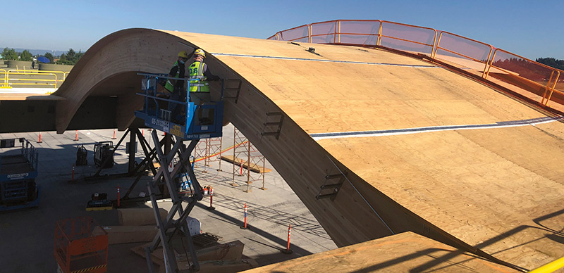
Above the glulam beams is a 2” thick MPP roof deck, technically a form of cross-laminated timber constructed out of wood veneer manufactured by Freres Lumber in Lyons, OR. This material had recently been developed and received APA product approval when the roof design was developing, and this represents the most prominent, and most publicly visible MPP project. To accommodate the curved and warped vault/dome surfaces, with the top of glulam radiuses as small as 35’-0”, the MPP panels were bent from their flat manufactured geometry to conform with the top of glulam beams. This process required an extensive full-scale mock-up to confirm joint locations, geometry, and faceting. SMT’s digital construction subcontractor CADMakers used advanced 3D modeling and detailing technology commonly used for aerospace industry manufacturing to determine the correct cut geometry for the panels. At the end of this pre-construction process, the panels successfully fit together with impressive precision on the roof structure. Additionally, the roof edge parapets and skylight curbs were constructed using MPP in place of cold-formed metal framing and sheathing, taking advantage of the in-line CNC capabilities of Freres to ensure proper fit-up while saving cost and schedule.
Erection Concept
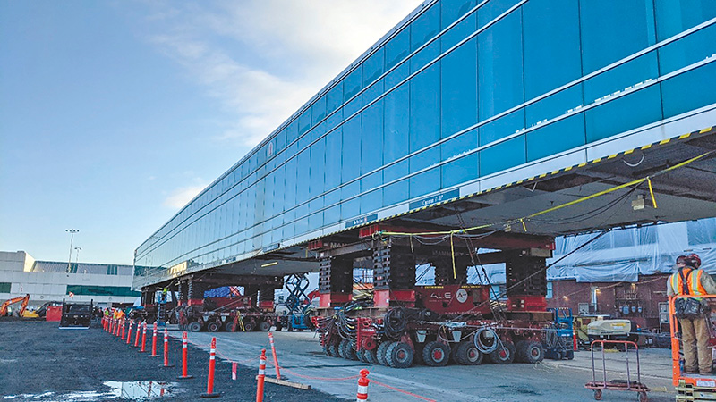
The TCORE roof design was inextricably linked with the erection concept, driven by the need to minimize impacts on airport operations. The roof erection planning and engineering process involved the Port of Portland, KPFF, HSJV, WW/AFCO Steel Trade Partners, Erectors Derr and Gruenewald, Mammoet Heavy Movers, and Walter P. Moore erection engineers forming a truly integrated team. Based on bridge launching techniques, a modular pre-fabrication approach was selected for the main roof. The 9-acre roof structure is separated into a total of (18) roof modules, (14) of which have been erected in Phase 1, with two each at the north and south ends of the roof to be installed in Phase 2 once the existing security node areas are closed. Construction over and in an occupied transportation hub is a major challenge, as activity continues throughout the 24-hour daily schedule. However, the Port worked with HSJV and the key stakeholders at PDX to identify short windows in the middle of the night when limited portions of the terminal could be de-occupied as required by the City of Portland requirements below moving loads. The key to success was limiting the overall operational impacts, which was accomplished by minimizing the quantity and duration of roof moves over occupied terminal areas.
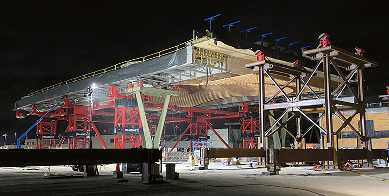
The roof includes (9) “super-modules,” which are up to 235’ long by 155’ wide and weigh up to 1400 kips, featuring a 20’ double steel girder section on each side of an 80’ wide timber section, with timber cantilever beams extending off one side at some locations. Each of the (5) Phase 1 roof modules that occur over the existing terminal were jacked up to elevation in the prefab yard, transported on a Self-Propelled Modular Transport (SPMT), then launched over Y-columns and temporary shoring towers supported by existing columns that have been demolished to just above the main floor level. Each launching support featured a custom pivoting slide support assembly with an integrated jack for elevation control and load monitoring and was propelled by a strand jack setup with one end temporarily anchored to a Y-column and the other fastened to the trailing end of the roof girder. Using this approach, the modules were pulled into their final position, temporarily cantilevering up to 70’ to reach the next support. Through this methodology, the operational impacts of each of the (5) modules erected over the terminal were limited to a few short-duration partial night closures, allowing the airport to continue uninterrupted operation while being transformed into the terminal of the future.
In the 80’ wide gaps between any (2) super-modules, all-wood “drawer” modules, with each glulam beam end supported on roller assemblies, were temporarily linked together by struts and slid into place along the bottom flanges of the erected roof modules and into final position, where they were bolted into place on the module girders, permanently tying the roof together into a cohesive whole.
Moving Structures/Temporary Bypasses
Routing passengers through the airport during construction offered major challenges for the project. To ensure a quality passenger experience, the team came up with a creative solution to re-purpose the existing Concourse Corridor Connector (CCC), a roughly 700’ long existing structure built in 2003 to connect Concourses C and D, which was slated for demolition as part of TCORE. KPFF had initially designed the CCC as a continuous bridge-like Vierendeel truss structure with a series of approximately 100’ long spans to allow for flexibility below. This structure was cut into two segments, with approximately half relocated to the north and south ends of the terminal, where temporary supports were erected, with tie-ins to the existing Concourses on each side of the TCORE construction area, allowing for passenger routing through a safe, pleasant facility during both Phases 1 and 2. This structure relocation also provided an opportunity for the project’s heavy mover, Mammoet, to showcase their capabilities, as they used their SPMTs to lift and drive the 300’+ long segments around the existing terminal and concourses and set them on their temporary supports during a short overnight window.
Sustainable Wood Sourcing
The use of local, sustainable wood was a high priority for the Port, which worked with ZGF and partnered with Sustainable Northwest Wood to develop a novel and detailed plan for sourcing and tracking wood from a variety of sustainable sources, including regional indigenous-owned lands and small family-owned forests. The team worked tirelessly with every partner to optimize the supply chain, trailblazing a new path for sustainable wood sourcing through constant market inertial resistance and allowing such detailed tracking that they could pinpoint the origin of nearly 100% of the wood in the roof structure on an element-by-element basis, ensuring it was all sustainably sourced.
Through touring numerous forests and meeting with sawmills, lam stock processors, manufacturers, and fabricators, the team heard “I don’t know if this is possible” and “this has never been done before” countless times. Still, with the support of the Port, the team chipped away at the reluctance and uncertainty. It achieved the project goals of sustainable sourcing without paying significant premiums for fully certified lumber, which also wasn’t available in the volumes required for the project. Through this process, the team showed the market what is possible and created a new case study for flexible and achievable sustainable wood sourcing, which can be replicated on many future projects. Through Life-Cycle Analysis, the team was able to quantify a massive overall reduction in project-wide embodied carbon through use of sustainably-sourced wood.
Conclusion:
Every significant project presents challenges, and it’s our job as structural engineers to work with our project teams to find the appropriate creative solutions and help implement them safely, efficiently, and cost-effectively. The TCORE project, as both a massive expansion and retrofit of an existing operating transportation hub, presented tremendous obstacles that called for unique solutions. By pushing the state of the practice using cutting-edge analytical tools, physical testing, and novel construction methods, along with plenty of good-old-fashioned effort and teamwork, the KPFF team has contributed significantly to the delivery of a structure that the project team, Port of Portland, and the local community can be proud of for generations to come. Book your flights now to/from PDX for Summer 2024, when Phase 1 will be open to the public, and enjoy this iconic transformed terminal; trust us, you’ll want to celebrate with us by “raising the roof”!■