
Structural design considerations for rooftop equipment platforms.
Supporting rooftop mechanical or electrical units is a simple problem with a complicated solution. While some units are small and light enough to bear on the roof with minimal additional support, many require supplemental structural roof framing. Depending on the building structural system below, the units may be supported on a pad or curbs, sleepers or loose dunnage, or raised platforms. Typically, the term dunnage has been used interchangeably with raised platforms. Still, it is more accurate to say that dunnage consists of loose structural members that distribute the unit’s load over the existing roof without penetrating the roof membrane. These members are not connected to existing roof structural framing.
Raised mechanical platforms are steel-framed structures added to the roofs of new and existing buildings. These platforms provide support for the units and maintenance walkways between each unit. They are supported on posts bearing on the base building structure. These raised platforms are sometimes not considered part of the base building structural system and are often added while upgrading or updating the building mechanical equipment. This article reviews the design procedure for raised mechanical platforms.
Geometry
The design of raised mechanical platforms is frequently driven by geometric constraints of both the building below and the units themselves. It is best to install platforms away from building edges and roof drains, if possible, to avoid complications with facade attachments. However, if avoiding a roof drain is not feasible, the roof drain may need to be moved to accommodate the platform post.
Existing roofs typically do not have the reserve capacity to support large mechanical unit loads added after the original construction. Therefore it is common to support the units on new elevated equipment frames, which typically post down to the top of existing columns. Columns tend to have additional capacity compared to horizontal roof framing.
The platform must be tall enough to accommodate potential reroofing and any ducts that run below it or other equipment that may be anchored directly to the roof. The National Roofing Contractors Association (NRCA) Roofing Manual for Membrane Roof Systems recommends the following clearances under the platform to allow for roofing:
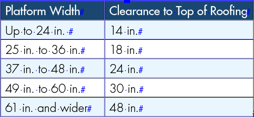
Where ducts run below the edge of the platform, the kickers that provide lateral load resistance must be clear of the duct, which may necessitate a further increase in height. If there are no ducts or the duct height is minimal, the platform should be raised high enough to ensure that the bottom of the steel is above the top of the flat roof snow height so that snow will not drift against the platform structure. Starting with the 2016 edition of ASCE 7, Minimum Design Loads and Associated Criteria for Buildings and Other Structures, Section 7.8 specifies that drift loads may be ignored only when the bottom of the platform or other projection is at least 2 feet above the balanced snow load height.
The platform plan geometry and framing are primarily driven by the equipment on the platform and require close coordination between the design team and Mechanical Contractor. Framing must be provided under the perimeter of the equipment and any intermediate supports. Some equipment, such as cooling towers, generators, and air-handling units, have fixed projections below the equipment that framing must avoid, like piping, conduits, and ducts.
Walkway widths should be at least 3.5 feet for access and service. In addition, service clearances for replacing coils or filters are sometimes needed. Typically, these clearances are the width of the unit and occur on one side of the unit. Sometimes removable guards can provide the necessary clearance and limit platform size. These removable guards will require additional maintenance.
Construction/Detailing Considerations
As discussed above, it is best to align platform posts with the building’s columns. While posting off roof framing is possible, the roof framing or connections likely require reinforcement for strength or stiffness.
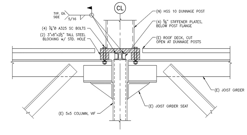
Typically, a cap plate can be added to the top of the column, and the post is either welded or bolted to this plate. The post base connection detail and post lengths must account for the roof pitch where the roof framing slopes. In open web steel joist construction, the joists and joist girders typically bear on top of the column, complicating adding a post above the column. The authors have successfully used the detail shown in Figure 1 to bolster the column in joist construction.
To attach to the framing below, the posts must penetrate the existing roof to support the platform. Round or rectangular posts allow for better flashing of the post into the roof membrane. Wide flange posts are significantly more difficult to flash and should be avoided unless round or rectangular posts are not available or feasible due to other constraints. If wide flange posts are needed, plates can be welded between the flanges to create a rectangular base that allows flashing.
In addition to waterproofing, the design team must consider the thermal bridge created when the platform posts penetrate the roof insulation. The architect, envelope consultant, and mechanical engineer should review the impacts of this bridge and determine whether a thermal break should be provided. Thermal breaks may be achieved by adding load-bearing insulation material within the insulation layer of the roof or adding a thermal coating to the post and the supporting framing near the post. Many thermal breaks will require special detailing to transfer lateral loads into the roof structure.
Because mechanical platforms are exposed to weather, the framing is commonly hot-dip galvanized. High-performance coatings are sometimes used for architectural reasons. Field welded connections (i.e., moment connections) should be avoided, since they require field touch-up of the galvanized coating with zinc rich paint. This zinc rich paint touch-up is inherently less robust and less abrasion resistant than shop-applied galvanizing and may have a shorter service life. Vent holes in hot-dip galvanized posts must be plugged after galvanizing since unplugged holes are a potential source of water intrusion into the building. All cap plates should be seal welded to avoid leakage
Equipment supports are typically bolted to the supporting beams. In general, beams should have at least a 6-inch wide flange for equipment and grating support; however, certain equipment, such as spring isolators, may require a significantly wider supporting flange.
When desired, the typical walking surface for a raised platform is metal bar grating. Standard grating is 19-W-4, which is welded bearing bars at 13/16 inch on-center, with cross bars at 4 inches on-center. Use fully banded panels to avoid sharp edges at the ends of bearing bars. The grating should be manufactured in a maximum of 3 foot wide increments to allow it to be removed and adjusted in the future, if necessary. Use bolted saddle clips to facilitate future removal.
The owner may prefer serrated platform grating for improved slip resistance. Serrated grating is manufactured by cutting ¼ inch notches in deeper bearing bars, so 1½ inch serrated grating has similar structural properties to 1¼ inch non-serrated grating. Depending on the project parameters, this can result in around 10% – 20% additional material for serrated grating to have the same structural performance as non-serrated grating. Due to added material cost, the decision of whether to provide serrated grating should be discussed with the owner and end-users of the platform. OSHA does not require serrated grating, and there is little definitive published information on the need for serrated grating on these platforms.
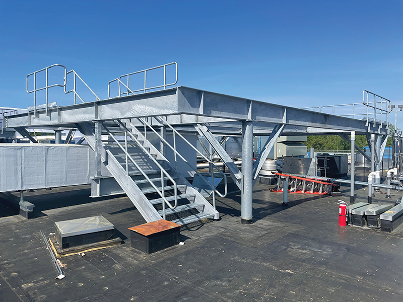
Platforms with grating require access using a ladder or stairs. Stairs are more common because they make bringing large objects onto the platform easier when servicing the units. However, to facilitate future re-roofing, stairs should not bear directly on the roof. Instead, they should be hung from the platform with a gap (typically 3 inches) between the stair stringer and the top of the roofing. Figure 2 is an example of a hung stair.
Guards are required for most platforms with a walking surface 30 inches above the adjacent surface.
Some platforms and equipment require visual and/or acoustic screening. It is common for these screens to be extended 10 feet or more above the platform, which can induce significant wind load on the platform. For visual screening, the use of perforated screens may slightly reduce the added wind load; however, the Authors recommend designing the platform assuming a solid screen in the event the owner changes the screen in the future. Visual screens do not need to extend below the platform framing since the platform framing is often out of the sight lines from ground level. Set the bottom of the screen elevation to avoid inducing snow drift on the roof framing. Visual screens typically weigh approximately 3 – 5 psf, but this value should be confirmed during design.
Acoustic screens typically extend close to the roofing to mitigate sound projecting from equipment; however, this lower extension will create a snow drift against the screen that must be considered when evaluating the base building structure. Acoustic screens typically weigh approximately 10 – 12 psf to improve their sound impedance.
Bracing for these screens requires close coordination with the project team. Installing braces (sometimes called kickers) back into the platform is an option; however, they may clash with equipment and walkway service clearance. Using vertically cantilevered posts is possible, but this method increases the platform weight. Typically, wide flange posts are needed since round and rectangular posts usually cannot accommodate such large cantilever heights.
Visual and acoustic screening material typically lacks published in-plane strength, making it difficult assume it behaves as a vertical diaphragm for in-plane loads on the screen wall. Therefore it is necessary to provide vertical bracing within the plane of screen walls. Unfortunately, this is sometimes an overlooked detail that significantly affects the in-plane stiffness of the screen.
Special Loading Considerations
Wind loading on equipment platforms can be significant. ASCE 7-16 requires platforms to be evaluated for an amplified wind load due to localized pressures, as calculated in Section 29.4.1. Wind loads act on equipment and the webs of the framing members, causing weak-axis bending of those members.
There are currently no explicit provisions in ASCE 7 to account for shielding of the units from wind load. Neglecting shielding and assuming a full wind load on each unit simultaneously may be overly conservative. Based on research by R.E. Whitbread on the influence of shielding for wind pressures on arrays of lattice frames, similar shielding can be extrapolated for rooftop units, which gives more practical overall wind loads. From Whitbread’s research, generally, if units are grouped so that the space between units is less than or equal to the height of the units, the leading unit can shield up to 50% of the total wind load on the trailing unit. It is important to consider that equipment could be removed or replaced in the future, which would change the loading pattern. Therefore, where shielding is considered for the overall platform design, it is necessary to locally evaluate framing supporting equipment ignoring shielding.
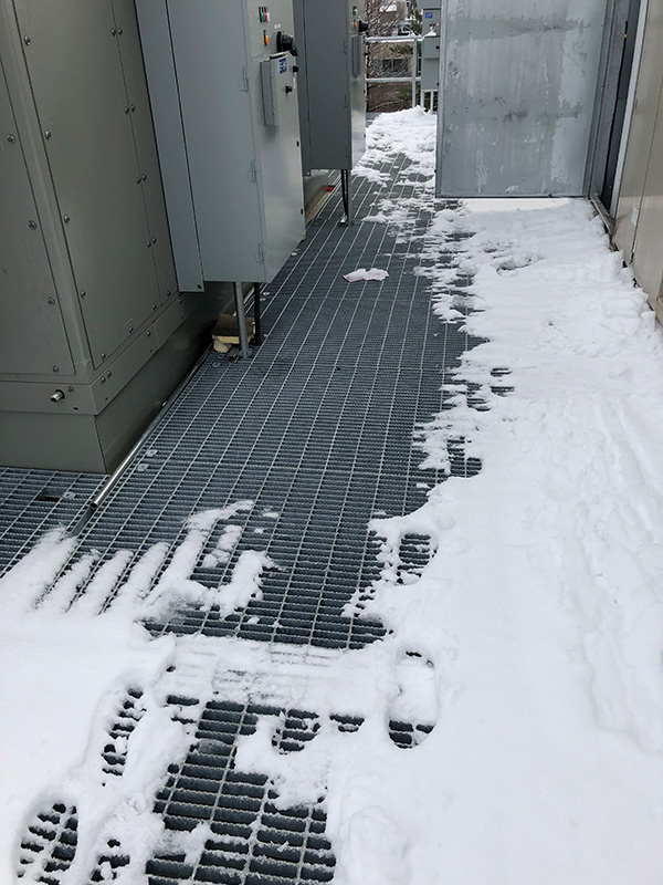
While grated platforms are not solid surfaces, snow can bridge over the gaps in the grating, and snow loading should be assumed to build up on the grating. Figure 3 shows an example of snow bridging gaps on a grated platform. ASCE 7-16 Section 7.13 requires grating to be considered as a solid surface for snow loads because of the cornicing (bridging) between bearing bars.
Design Considerations
Because of the durability issues noted above, the lateral load resisting system (LLRS) for platforms should strive to use bolted connections whenever possible. It is common for lateral systems to consist of bolted knee braces, also called kickers, which are typically double or single angles. To accommodate flashing the posts, the work point of the knee brace is usually 18 in. to 24 inches above the top of the roof structure, allowing for roof insulation depth. Bolted moment connections are an option, but grating can conflict with the bolted connections. Shop welded moment connections or use of continuous framing (i.e., beam-over-column) are also options.
The geometry of knee braces is such that, under both gravity and lateral loads, the knee-braced joints can have significant horizontal forces at the top and bottom of the post (i.e., the post connection to the roof structure below and the post-to-beam connection above). In particular, the post connection to the roof framing and the transfer of horizontal forces into the roof diaphragm must be checked. In addition, platform beam-to-post connections must be designed for the horizontal axial forces in the joint.
A staged construction approach could be used in which the kickers are installed after equipment and other permanent dead loads to reduce the horizontal demand under gravity loading. However, this method results in a complicated analysis and construction approach and should be avoided for most platforms.
The diaphragm for platforms typically utilizes horizontal plan bracing to resist in-plane lateral loads. Grating cannot act as a diaphragm because it has relatively little in-plane stiffness, is discontinuous, and is not usually permanently fastened. For small platforms, it may be possible to transfer in-plane loads through weak-axis loading of connections; however, this requires careful connection detailing and is typically impractical for platforms with even marginal lateral loads.
Framing that supports equipment is typically designed to more stringent deflection criteria than those in the International Building Code. Most units have operable doors or are assembled from segments in the field. Framing that is too flexible will cause doors to jam or prevent bolting. In the authors’ experience, the maximum framing differential deflection along a unit should not exceed ½ inch. However, more or less stringent requirements should be reviewed and coordinated with the equipment manufacturer. Equipment weight may be modified during design coordination, so consider designing framing to have reserve capacity.
Conclusion
The structural design of equipment platforms is a detail-oriented engineering exercise for these unique structures. A successful design relies on understanding the equipment on the platform and the end use of the platform, which can be achieved through close coordination with the project team and platform end users.■
References
Whitbread, R.E. 1980. The Influence of Shielding on the Wind Forces Experienced by Arrays of Lattice Frames. Teddington, UK: National Maritime Institute.