
Recently, it became fairly apparent that construction cost of affordable housing – using current building codes and models – is quite high on a unit cost basis. This cost issue reduces the number of units available and makes them prohibitively expensive for many potential buyers. However, current knowledge enables construction of multi-story concrete flat plate buildings of optimum cost. Typically, sixty to eighty percent of structural concrete volume in a multi-story flat plate building goes in slabs. In the U.S., it is typical for multi-story residential buildings to be post-tensioned concrete construction, typically with 8 inch (203 mm) thick slabs spanning up to 30 feet (9.1 m) between columns and/or bearing walls. This framing system layout provides architects with flexibility in room and unit layout on a given floor, and in adjacent stories, since the unit walls are not required to stack, as is the case in economical multi-story wood frame construction. Structural engineers have long known that greater number of columns reduces both the slab spans and the overall cost of construction; shorter spans allow for using thinner slabs.

Minimizing the slab thickness optimizes the cost, particularly if floor plans are not expected to change during the lifespan of the structure. However, vulnerability to punching failure and excessive long-term deflection must be addressed. Design for punching using stud-rails (Dilger and Ghali 1981) solves the vulnerability to punching shear failure. A stud-rail is an assembly of mechanically anchored steel studs (ACI 421.1R-20, Guide to Shear Reinforcement for Slabs). Idealization of flat plates as grids with simple frame analysis or use of finite-element method, combined with the current knowledge of cracking, creep and shrinkage of concrete, and relaxation of prestressing reinforcement, gives accurate prediction of long-term deflection (Ghali and Gayed 2019). Research conducted on this concept shows that a 5-inch (127 mm) slab thickness is adequate for punching shear strength and to avoid excessive long-term deflection for 16.4 foot (5 m) spans between columns. The same thickness with post-tensioning is adequate for spans up to 22 feet (6.7 m), with the long-term deflection controlled to a desirable limit with appropriate stressing.
Typical Flat Plate Interior Panel
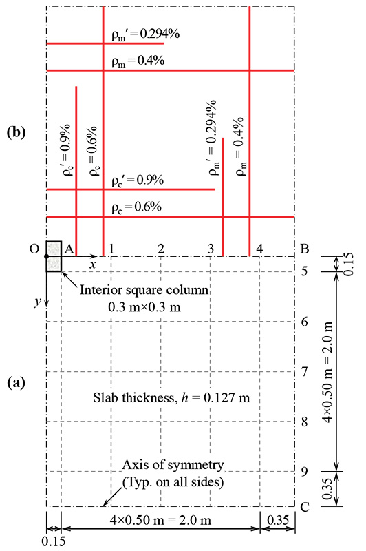
Figures 1 and 2 show plan views of a typical interior flat plate panel measuring 16.4 × 16.4 feet (5 × 5 m) with thickness, h = 5 inches (127 mm), supported on square columns of side dimension 11.8 inches (300 mm) with concrete compressive strength, f’c= 5.1 ksi (35 MPa) and typical interior and edge column-slab connections; the story height, lc = 9.83 feet (3 m). For seismic design, consider DRu = 0.018; where DRu is the ultimate story drift divided by the story height. This corresponds to an elastic drift, δe = 0.663 in (17 mm) (ASCE/SEI 7). Take the service gravity dead loads = 𝛾h plus 20.9 psf (1.00 kPa) super-imposed dead load; with 𝛾 = 153 pcf (24 kN/m3); live load = 40 psf (1.9 kPa). Load factors and combinations in Section 5.3 of ACI 318-19 are used.
(1 m = 1000 mm = 39.37 in. = 3.28 ft; 1 kN = 224.8 lb; 1 kN-m = 8.851 kip-in.)
Punching Shear Strength
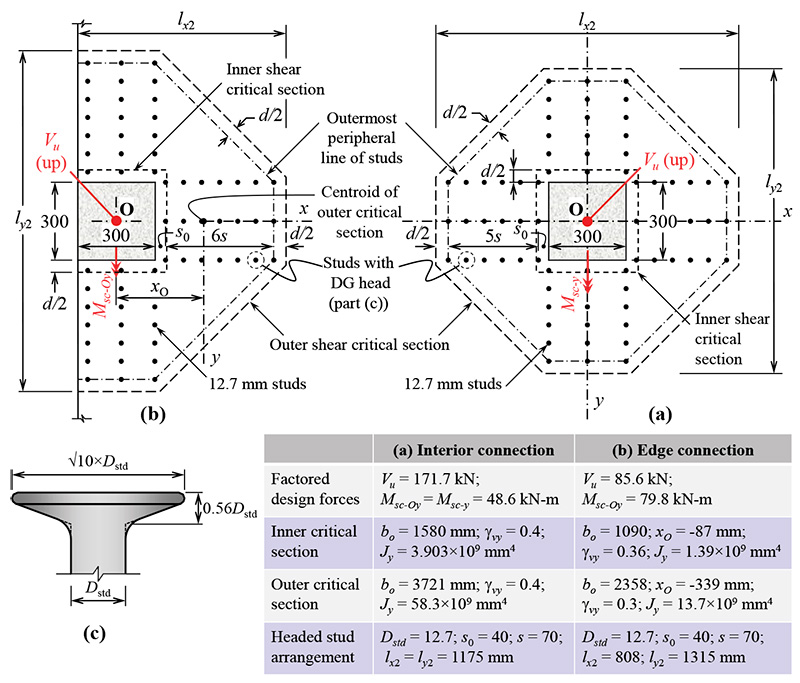
The effective depth of the slab is d = 3.74 inches (95 mm). In the current section, design rules of stud-rails with DG anchor heads (Dilger and Ghali 1981; Figure 2c), conforming to ASTM A1044/A1044M in ACI 421.1R-20 and ACI 421.2R-10 are applied at typical interior and edge columns. Figures 2a and 2b show the arrangement of the shear critical sections and the headed studs that ensure adequate punching shear strength at the interior and edge column connections, respectively. This design is adequate for an earthquke with an inelastic story drift ratio = 1.8%.
Shear stress at interior or exterior shear critical section, due to the transfer of factored shearing force, Vu combined with moments Msc−x and/or Msc−y is calculated by:
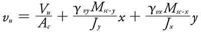
where Ac = bo d = area of shear critical section; bo = perimeter length of shear critical section; 𝛾vx or 𝛾vy = fraction of moment about x or y-axis that is transferred by shear stress at the assumed shear critical section; Jx or Jy = property of shear critical section equal to d multiplied by second moment of perimeter about x or y-axis; (x, y) = coordinates of point on perimeter of the shear critical section with respect to centroidal principal x and y axes. At edge columns, the centroid of the shear critical section does not coincide with that of the column, O; the slab moments, Msc−x and Msc−y about x and y-axis through the centroid of the shear critical section is related to the slab moments, Msc−Ox and Msc−Oyabout x and y-axis through O by:
Msc-x = Msc–Ox + Vu yO ; Msc-y = Msc-Oy + VuxO
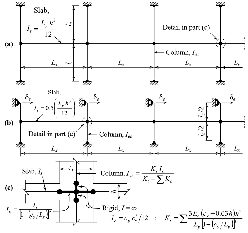
Vu = factored shearing force; (xO, yO) = coordinates of O with respect to the centroid of the shear critical section along the centroidal principal x and y axes. By elastic analysis of the frame in Fig. 3a subjected to gravity loads, determine the values of Vu and Msc−Ox and/or Msc−Oy; for seismic design, employ the equivalent frame in Fig. 3b.
Long-Term Deflection
The example slab has flexural reinforcement ratios, 𝜌 and 𝜌‘ in the column and middle strips as shown in Fig. 1b. During construction, the slab is subjected to a uniformly distributed load, qc = 133 psf (6.38 kPa); in service, the quasi-permanent distributed load on the slab is
qp = 104 psf (5.00 kPa). The analysis procedure and equations are given in details in Ghali and Gayed 2019 and Gayed and Ghali 2022 (Chapter 6). The time-dependent material parameters are: t0 = 28 days; t = ∞; creep coefficient, φ(t,t0) = 2.491; aging coefficient, χ(t,t0) = 0.872; free shrinkage strain, εcs(t,t0) = −300 × 10-6. Other data: moduli of elasticity of the concrete and reinforcing steel are: Ec (t0) = 4.34 × 10³ ksi (28.0 GPa) and Es= 29 × 103 ksi (200 GPa), respectively; the concrete tensile strength, fr = 326 psi (2.247 MPa); Poisson’s ratio, v = 0.2.
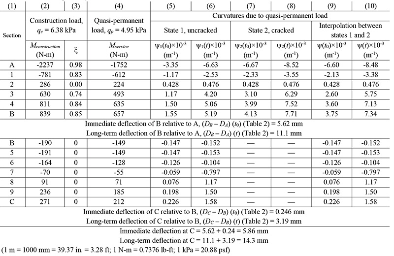
The computer program EGRID (Gayed and Ghali 2022) idealizes the flat plate panel as a grid of torsionless beam elements; the results of the analysis are in Table 1 (columns 2 and 4). Deflections at times t0 and t are calculated in Tables 1 and 2; the immediate and long-term deflections at Point C are 0.231 and 0.563 in (5.86 and 14.3 mm), respectively, corresponding to span/853 and span/350, respectively. For slightly longer spans, larger deflection can be counterbalanced by camber in the formwork.
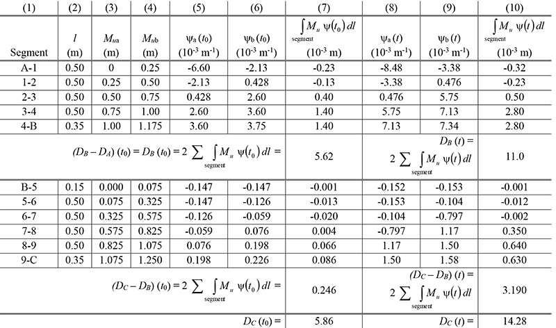
Note: Deflection at any intermediate point C on a beam can be evaluated numerically as:
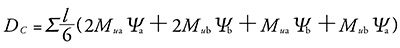 where Mu = bending moment due to a unit downward force at C. The summation is for all the beam segments. Mu and 𝜓 vary linearly over length of a typical segment with length = l and ends at a and b. (1 m = 1000 mm = 39.37 in. = 3.28 ft)
Code Requirements
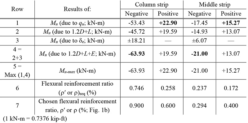
For the flat plate considered, ACI 318-19 requires a minimum slab thickness = ln/33 = 5.63 inches (143 mm). The code allows the chosen thickness 5 inch (127 mm) thickness because calculations showed its adequacy for the punching shear strength at the slab-column connections and the long-term deflection. Table 3 shows that the flexural reinforcements in Fig. 1b satisfy the flexural strength requirements under gravity and earthquake loads of the code.
Cost
The Canadian Cost Guide 2022 gives market value per square foot in Canada with common quality of finishing work in the range CAD $400-500, which is roughly US $300-365. With the optimum cost saving presented, the cost of the elevated structure per square foot can be reduced by 60 percent. If the cost of the elevated structure is assumed to be 25% of the total project construction cost, the overall saving to the project is 15%.
Conclusion
The DG anchor head at both ends of studs arranged in a crucifix layout in the vicinity of columns ensures punching safety. Current knowledge of creep, and shrinkage of concrete and relaxation of prestressing reinforcement is adequate to predict long-term deflection of floors.