
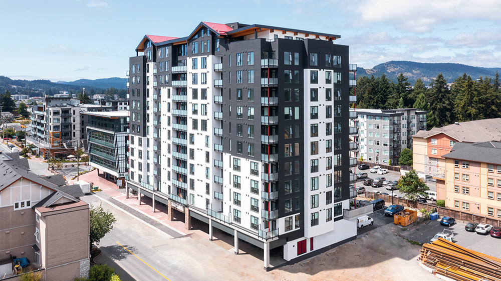
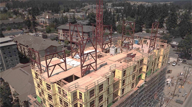
Tallwood 1 at District 56 is a twelve-story mixed-use mass timber building located in Langford, British Columbia, Canada, designed by Design Build Services (DBS), Jack James Architecture, and Aspect Structural Engineers (Figure 1). Tall wood construction is a relatively new typology across North America, and this building is the first structure to be constructed under the British Columbia Building Code’s (BCBC) new Encapsulated Mass Timber Construction (EMTC) provisions, a typology that drastically reduces a building’s structural embodied carbon. EMTC is very similar in limitations and fire requirements to the 2021 IBC Type IV-B construction type. As appropriate to a novel system, the design and construction of this building presented some significant challenges and valuable lessons along the way, with one of the primary challenges being the building’s location: Langford is located in the Cascadia Subduction Zone, a region that is among the highest in seismic demand in all of Canada. Tallwood 1 was the tallest steel-timber hybrid structure in Canada when it was completed in 2021.
Project description
Tallwood 1 includes eleven stories of residential rental units over one story of retail commercial units and two levels of underground parking. Below grade construction and a single-story podium are constructed of cast-in-place reinforced concrete, while the upper levels consist of hybrid mass timber and steel construction. This project was purpose-designed for mass timber from the outset, allowing the early decisions, including grid layouts, lateral load resisting options, and floor-to-floor heights, to be set up appropriately for mass timber. Trying to adapt mass timber to a concrete schematic design is the bigger challenge and can be the reason a mass timber building may not end up being cost competitive.
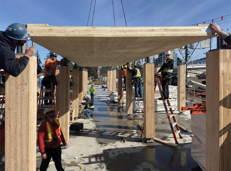
One of the team’s goals was to enhance the speed of construction of the timber superstructure relative to cast-in-place concrete construction, which is otherwise standard in the region for buildings taller than six stories. To achieve this goal, prefabricated mass timber and steel elements with simple, repeatable, and pre-installed connectors were used as much as possible to eliminate the need for temporary formwork, shoring/reshoring, and concrete strength gain. Floor elements were mostly panelized, while members of the lateral force resisting system were pre-assembled into larger segments prior to delivery to the site.
Gravity framing
The typical floor plate at the residential levels consists of point-supported, two-way spanning Cross Laminated Timber (CLT) panels supplied by Structurlam Mass Timber Corporation (SMTC). Point-supported CLT involves CLT supported only by columns, eliminating all or most of the beams from the floor plate and resulting in a flat plate structure that is fast to build and easy to coordinate with architectural, mechanical, and plumbing requirements. The downside of point-supported CLT is that it requires a very tight column grid that is entirely dependent on the available CLT panel sizes. SMTC produces CLT panel dimensions of up to 40 feet (twelve meters) long and 9.84 feet (three meters) wide, driving the column grid layout of 9.84 feet × 11.81 feet (3 meters by 3.6 meters). Knowing the range of mass timber panel sizes available from different suppliers helps inform early decisions like column grid layouts.
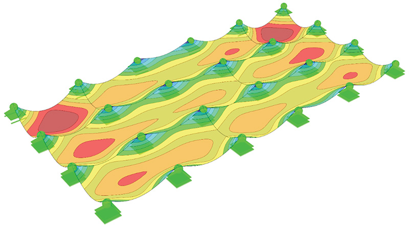
CLT panels are built up of layers of dimensional lumber that are laid flat and glued together, with alternating grain directions in each layer. The alternating layer directions allow the panels to span in two directions, giving the panels major and minor strength directions. The major strength direction, the direction parallel to the outer laminations of lumber, coincides with the long direction for the SMTC panels used.
The final structure used the CLT panels as two- and three-span continuous members in the panel’s long direction, with 11.81-foot (3.6-meter) spans in the major strength direction. No bending moment continuity was provided at panel-to-panel joints, so the panels had a single 9.84-foot (3-meter) span in the minor strength direction. Deflection and flexural strength in the minor strength direction ultimately governed the overall panel thickness of 6.89 inches (175 millimeters). The stiffness and strength properties for the panels were calculated in accordance with Canadian Standard Association (CSA) O86:19 Engineering Design in Wood, which introduced CLT design provisions in the 2014 edition.
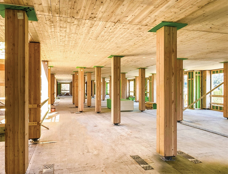
Floor panels were supported on Douglas Fir glue-laminated timber columns which provided support for ten stories of residential construction. Column sizes ranged from 10.35 inch × 10.47 inch (263mm × 266mm) at the higher levels to 12.36 inch × 11.97 inch (314mm × 304 mm) at the lowest levels, and were kept consistent within each floor.
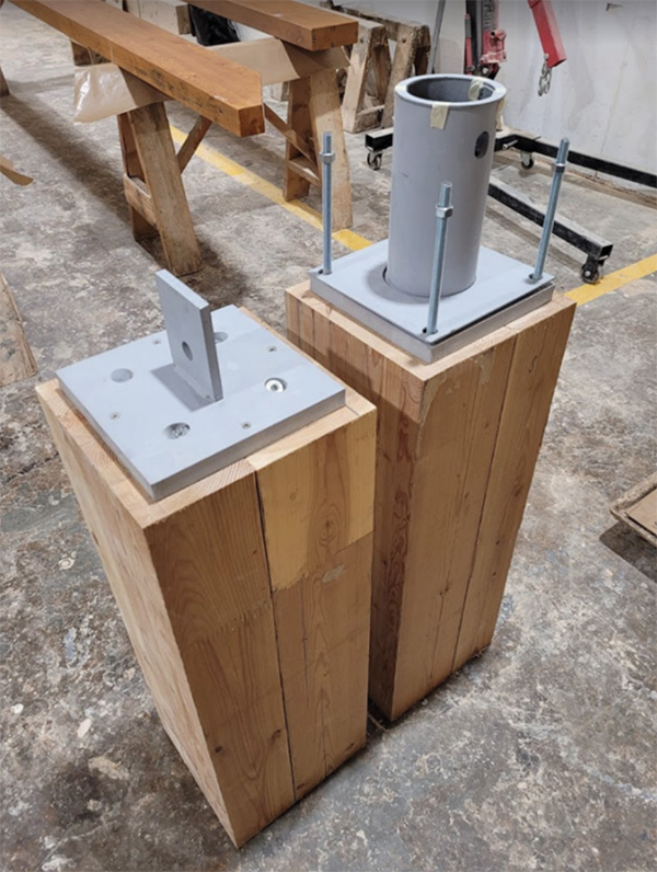
To avoid passing large compression forces through the floor structure and the associated cumulative perpendicular to grain wood crushing and shrinkage issues that might occur, column-to-column connections pass through the floor panels (Figure 3). Hollow steel structural section (HSS) stubs connected to the tops of columns allow for a reduced cross-section and provide a bearing area for the supported floor panels. Similarly, steel plates attached to the column bases slot into the HSS stubs below (Figure 4). This connector is used throughout the entire project at each column, with variations only for different column sizes. It fulfills many functions since it is largely shop-installed and easy to site-assemble, provides some key integrity to the structure via tension capacity, allows for deformation compatibility as the building drifts laterally under wind or seismic load, and avoids any perpendicular to grain shrinkage or wood crushing.
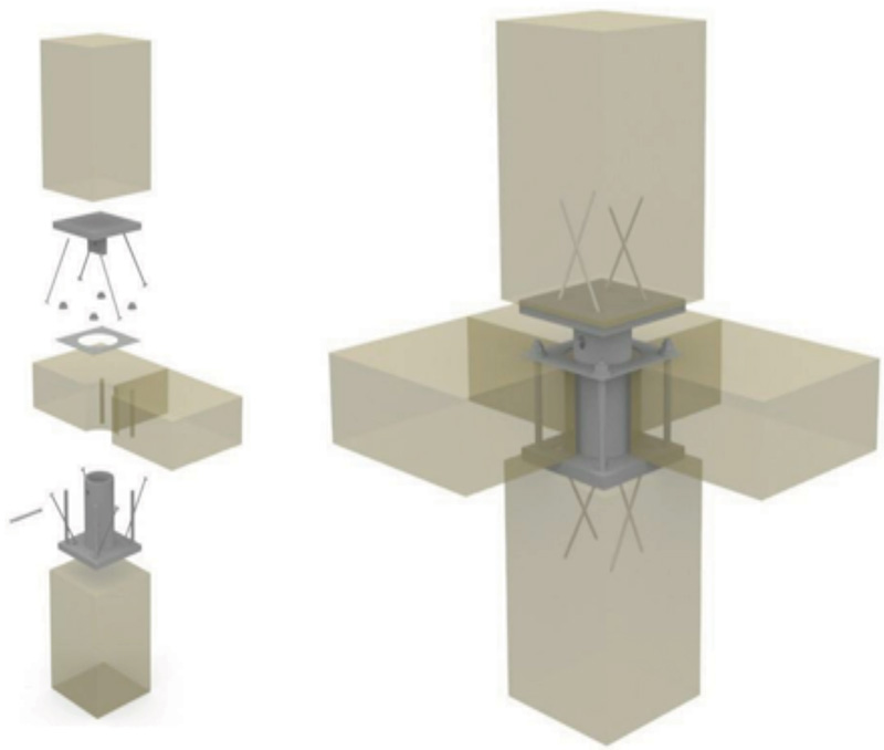
Analysis showed that over the height of the building, cumulative vertical deformation of the timber elements was relatively minor and managed at each level with site-installed steel shims at the column-to-column connectors with special attention paid to the columns closest to the steel braced frames. With perpendicular to grain bearing completely avoided, deformation was primarily due to elastic shortening of the columns, somewhat amplified by the effect of creep. Cumulative vertical shortening would be a bigger challenge for a taller building in the 18story (Type IV-A) range.
Punching shear failure, also known as rolling shear for mass timber, was an important design consideration for the CLT floor panels near the column supports. As CSA O86-19 does not include any design provisions for punching shear design of CLT (nor does the 2018 NDS), the panel’s ability to resist punching shear was determined in accordance with a design document by StoraEnso, which is itself based on research by Mestek (references are included in the online version of the article). If the provided bearing area at the column had not been sufficient to avoid rolling shear failure, larger steel column cap plates or reinforcing screws could have been explored to either increase the critical shear perimeter or increase the panel rolling shear capacity, respectively.
The rooftop penthouse structure deviated significantly from the typical floor plates and included much larger spans, sloped roofs, and vaulted ceilings more suitable to post and beam construction than point-supported CLT. The roof structure incorporated glulam beams and columns to accommodate the larger open floor spaces.
The eleven stories of timber construction are supported on a 23 5/8 inch-thick (600mm) reinforced concrete transfer slab at the second floor. The two levels of underground parking are also of reinforced concrete construction typically seen in the region, with two-way flat plate slabs supported on concrete columns.
Fire Protection
To meet the provisions of the EMTC construction type, all load-bearing structural elements were required to achieve a two-hour fire rating, either through encapsulation or a combination of encapsulation and charring. The structural timber members (CLT panels and glulam columns) are encapsulated with two layers of 5/8 inch (16 millimeter) thick Type X gypsum sheathing to provide 1 hour of fire resistance, while the remaining fire resistance was provided through charring of the wood members.
CSA O86-19 Annex B provides design guidance for determining char rates, reduced cross-section dimensions, and calculating member resistances and follows a very similar approach to NDS Technical Report 10. For the fire design of a charred section, the reduced cross-section resistance includes using a material resistance factor (𝜙) of 1.0, the mean strength rather than a specified strength, and a short-term load duration factor, which all increase the structural capacity compared to non-fire calculations. The load demands are specified loads, rather than factored (ultimate) loads. As a result, the fire case, including one hour of char, rarely governed the design of the mass timber elements.
The penthouse roof structure includes exposed mass timber over a large area, which does not comply directly with the EMTC requirements in the BCBC and required an alternative solution application submitted to the Authority Having Jurisdiction (Langford) to approve the code deviation and demonstrate compliance with the objectives and functional statements of the code. The application was approved, and member sizes at the penthouse were permitted to be un-encapsulated and designed for the full two hours of charring.
Lateral Force Resisting System
In very high seismic regions like Langford, mass timber lateral force resisting systems are neither practical nor code-compliant in taller buildings. Most tall timber buildings face a choice of a concrete core or steel-brace framed system. Since there is no one answer for all buildings, it is a worthwhile exercise to review the building size, location, local trades and standard practices, and the building’s unique structural needs. Concrete cores can be advantageous where a single core is adequate for the building and where there is sufficient lead time to pre-build the core, or the core can be slip-formed. However concrete cores tend to have much higher construction tolerances than mass timber or steel, and any misplacement of embeds can slow a project down. Steel is ideal when the floorplate requires a better distribution of lateral elements, to reduce diaphragm drag forces, and because the tolerances are better matched to mass timber tolerances. From a coordination and trades perspective, however, a steel lateral system requires a separate trade to be operating on site during the erection of the mass timber, and unless the steel and timber are modelled together in a single coordinated model, fabrication errors can be introduced.
One of the team’s main project goals was to increase the speed of construction through off-site prefabrication, with a desire that the erection pace of the lateral force resisting system would keep up with the timber installation. Tallwood 1 is also located in a region with very large seismic demands which necessitated the use of a highly ductile lateral force resisting system. With these two constraints in mind, the design team opted to use an Eccentrically Braced Frame (EBF) system that would meet the building’s ductility needs, provide a good distribution of braces throughout the floorplate, and could be prefabricated and rapidly installed onsite.
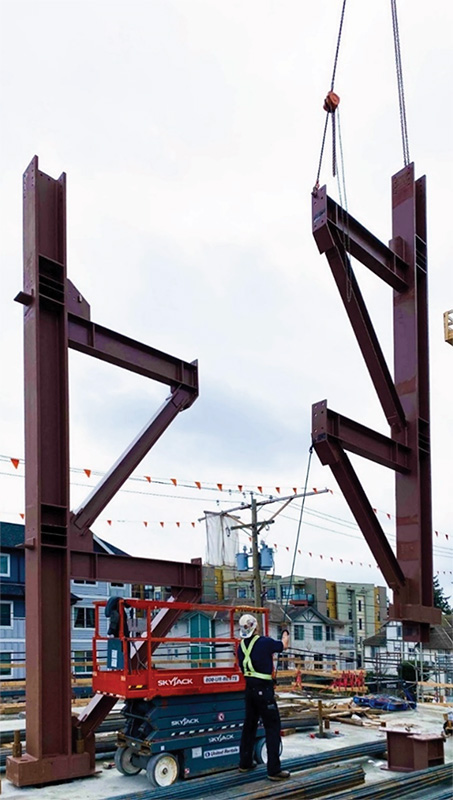
The EBFs have braces in a chevron configuration, but with the brace-to-beam work points offset from each other to create a short segment in the middle of the beam, referred to as the link, which can yield and remain stable while being subjected to very large inelastic displacement demands. Link members are sized to resist the factored seismic loads, and the remainder of the frame elements (beams, columns, and connections) are sized to resist forces associated with the links reaching their probable upper bound capacity. Link lengths were selected to ensure that the webs yielded in shear rather than in flexure, ensuring that yielding was not concentrated at brace-to-beam connections. Shorter links also result in greater overall frame stiffness prior to yielding. The steel fabricator shop-welded half-frames in multi-story segments (two or three stories at a time, depending on assembly weight and crane capacity) so that on-site assembly consisted of bolted connections limited to columns and link beams.
Avoiding structural concrete topping on this project kept the weight (and seismic mass) down, minimized the embodied carbon, and removed the sequencing challenge of a concrete diaphragm when concrete is unlikely to be poured after each level is erected. With only 1.5 inches of (38mm) gypcrete topping, the CLT panels make up the diaphragm. From a sequencing standpoint, a CLT diaphragm allows the diaphragm at each level to be installed and tied to the braced frames as timber erection proceeds, avoiding additional temporary column bracing or temporary diaphragm ties to ensure temporary stability during construction. The CLT panels are connected together in shear with plywood splines, and steel straps throughout the floorplate provide the chords and collectors, with collectors welded to the steel-braced frames.
Tall Wood Construction and Integrity
The BCBC and the Canadian Wood Code (CSA O86) both include a general requirement for structural integrity via interconnection of the structural members to resist progressive collapse of the structure. Integrity and resistance to progressive collapse are currently “baked” into the steel and concrete designs of tall buildings. Steel connections provide the necessary interconnectivity of elements in steel buildings, and measures like integrity reinforcement reduce the risk of widespread collapse of concrete buildings. Mass timber design of tall timber buildings, being a new typology across North America, does not yet have specific codified measures to ensure integrity is maintained. Looking to the Eurocode, however, provided options to achieve integrity. Tallwood 1 was designed using the “Tying Method” detailed by the Eurocode, which allows horizontal elements to be tied together in the event of a column being removed to prevent further collapse. The column-to-column details include a site-installed bolt connecting the upper and lower connection components together, allowing the columns to hang in tension if a column is damaged or destroyed. The steel diaphragm straps also provide further ties between the CLT panels, though these are intermittent.
Successes and Challenges During Construction
As in any project, an ounce of planning goes a long way but does not prevent unexpected and unwelcome surprises. The timber production and assembly were, as hoped, efficient and allowed for rapid assembly on site. The column-to-column connectors in particular allowed for quick erection of the timber elements and minimized crane time, the prefabricated braced frame segments were generally rapid to install and provided both temporary and permanent bracing to the timber as it went up, and the lack of structural concrete topping meant that a third structural material was not a critical path for the project sequencing.
One project challenge however was that the steel supplier and timber supplier each developed their own independent models and produced separate shop drawings; due to differences in timing between the two as well as the use of different software, the two models were not properly integrated, resulting in some relatively small tolerance issues that nevertheless required site welding and slowed construction somewhat. Ideally, the timber supplier “owns” the steel model and coordination to avoid this kind of slowdown.
Another challenge that was less foreseeable was the pandemic-related supply chain issue, familiar to so many working on projects constructed in 2020 and 2021. The original building design included exterior prefabricated wall panels that were to be installed by crane and allow the building to be enclosed as construction progressed. Wall panels are a critical path item because the BCBC requires that during construction of EMTC buildings, only four stories can be unencapsulated. To progress the timber structure higher, the stories four levels down must be encapsulated with gypsum wall board, and in order to protect the gypsum from moisture, exterior cladding is needed. Unable to receive the wall panels, DBS elected to site-build exterior wall panels, necessitating scaffolding to install them, and adding cost to the project as well as elongating the timeline.
Conclusion
Overall, Tallwood 1 was successfully completed and occupied in 2022, and it serves as an example for future tall mass timber projects in British Columbia and elsewhere. As tall wood structures become more common place, Canadian (and US) codes will further be refined to include specific guidance on topics such as cumulative vertical deformations, drift compatibility, and structural integrity. Until then, the design community can look to European code approaches, project precedents like this one and others, and good structural engineering practices and mass timber mechanics to ensure that tall wood buildings perform as well as any other building. Looking to past projects will also help future tall wood buildings avoid the coordination and workflow challenges to take full advantage of the speed of construction available with mass timber. With appropriate design and detailing, even in highly seismic regions, mass timber is an excellent choice for taller buildings.
References
British Columbia Building Code, Crown Publications, 2018.
CSA O86:19 Engineering Design in Wood, CSA Group, 2019.
Point Support of CLT – Analysis Sample and Theoretical Background, StoraEnso, 2014.
Mestek, D.P., Punktegestützte Flächentragwerke aus Brettsperrholz (BSP) – Schubmessung unter Berücksichtigung von SChubverstärkungen, München: Technische Universität München, 2011.