
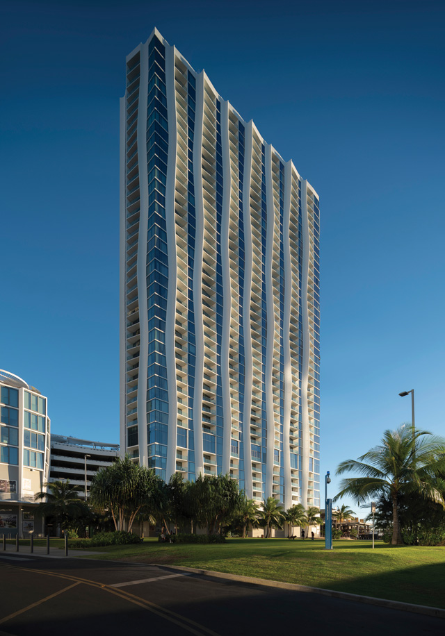
Kō‘ula is in the center of Ward Village, a 60-acre master-planned community in Honolulu’s urban core that was named “Master Planned Community of the Year” by The National Association of Home Builders and “Best-Planned Community in the United States” by Architectural Digest. Planned as a beautiful addition adjacent to the community’s central park, Kō‘ula is a 41-story mixed-use development featuring 942,000 square feet of built area, including a 566-unit residential tower, common and amenity spaces, 58,300 square feet of retail space, mechanical and support space, and six stories of above-grade parking.
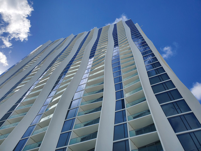
Kō‘ula, in native Hawaiian, means “red sugar cane” and inspired the undulating sculpted structural columns at its exterior façade, evoking the twisting structure of the sugar cane reeds that were formerly grown on plantations nearby. The unique design was created by internationally renowned architecture and urban design practice Studio Gang, led by MacArthur Fellow Jeanne Gang. According to Studio Gang, the building is designed from the inside out to seamlessly connect inhabitants with nature. Like many of the island’s native grasses that stretch toward the sun, the individual residences subtly peel off from the central core and angle themselves toward the coastline to capture views of the Pacific, the city, and the Ko‘olau Range. The columns, which were constructed entirely of reinforced concrete, were designed in collaboration with the engineer of record, BASE, and design-assist contractor, Hawaiian Dredging Construction Company, and were coordinated carefully with the architect to allow for the modularization of formwork and simplification of reinforcement while still providing an organic and unique defining architectural feature for the tower.
Behind the striking exterior, the structure primarily consists of post-tensioned concrete floor plates, reinforced concrete columns and shear walls. In the parking areas, long-span post-tensioned beams and floor slabs utilize a repetitive garage beam forming system to open the floor plan and maximize visibility, ventilation, and the space available for parking stalls. The garage beam system also allows for large column-free areas at the ground level for building support, mechanical areas, loading docks, and car drop-off for the retail spaces. This long-span system, combined with carefully spaced tower columns, also created relatively large column-free retail spaces that make up almost 50% of the ground floor area.
The tower itself is approximately 225 feet long in the north-south direction and 79 feet wide in the east-west direction. The tower’s lateral system consists of concrete shear walls around the elevators and stair cores to resist Honolulu’s hurricane-level winds and moderate seismic demands. Projects often utilize coupling beams made as deep as possible while maintaining minimum corridor height to connect the shear walls across corridors and limit building drift. However, due to the orientation and location of the tower’s shear walls as well as the limited floor-to-floor height provided, innovative shallow plate-reinforced composite link beams were implemented. In lieu of providing openings through the link beams, some beam depths were instead decreased further to allow mechanical and plumbing services to run under the coupling beam, reducing coordination efforts and minimizing or eliminating the chances for conflicts and clashes to arise between the structural, mechanical, and plumbing trades during construction.
Structure Supporting and Enhancing Space Planning
Maximizing the ocean views, ideally for all units, is one of the most significant design requirements for residential high-rise developments in the Ward Village neighborhood. In addition, development restrictions mandate that towers be oriented perpendicular to the ocean to avoid blocking view corridors to the ocean from the mountains and other buildings behind Ward Village. To overcome this requirement and provide all units with an ocean view, the architect laid out residential units with a portion of each unit protruding at an angle from the primary building mass with a broad face along its perimeter angled towards the ocean, referred to as a “podular” layout. The exterior columns, slab edge, and balconies are oriented in such a manner that each unit has both ocean views and privacy from their neighboring unit.
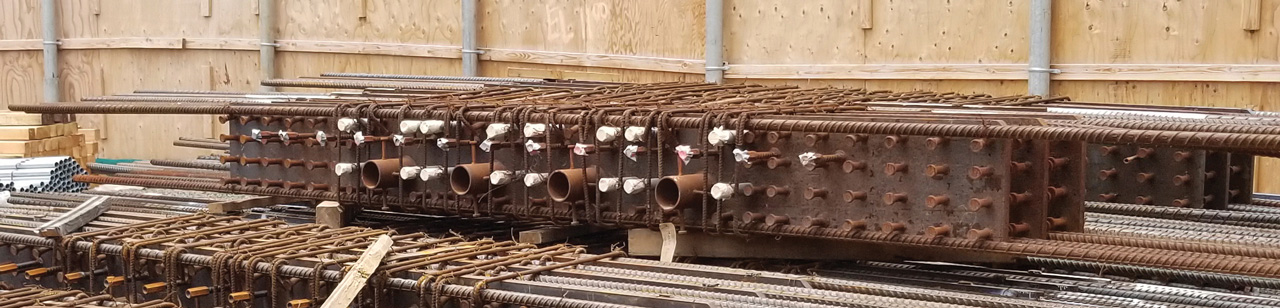
To create a welcoming drop-off area for residents, a full-height transfer girder is provided at Level 3 to increase space between columns at Level 2 and create room for a vehicular turnaround. This transfer girder is architecturally integrated as a backdrop to the adjacent open walkway connecting the tower and the adjoining mid-rise residential portion of the building and is ornamented with architectural screening and accent lighting.
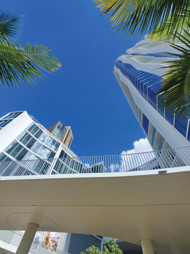
At Level 2, a new exterior courtyard was created with a view to interconnect the retail vehicular drop-off, tower entry, and access to the adjacent park to create a civic hub. This courtyard consists of a cantilevered walkway at Level 2 that connects the retail in the mid-rise building on the north side with the retail on the tower’s second floor overlooking the public park. Post-tensioning was essential in creating large terraces for gatherings and circulation that cantilever almost 15 feet from the supporting columns. An exposed concrete staircase within a large, organically-shaped oculus provides connectivity between Levels 1 and 2. This 45-foot-long staircase consists of a central conventionally-reinforced concrete spine beam with thin treads cantilevered to either side of the beam.
The exterior architectural columns continue uninterrupted from the foundation to the roof on three sides of the building, but on the east side, the tower façade is set over portions of the parking garage. This overlap requires columns on the east elevation to be terminated at Level 8, reshaped into rectangular columns, and rotated to provide adequate clearance for parking stalls. Most of these transitions are made with direct bearing on overlapping areas of columns below with additional compression dowels provided as required. Shallow beams are provided at more extreme transitions to transfer the overhanging column to its supports below.
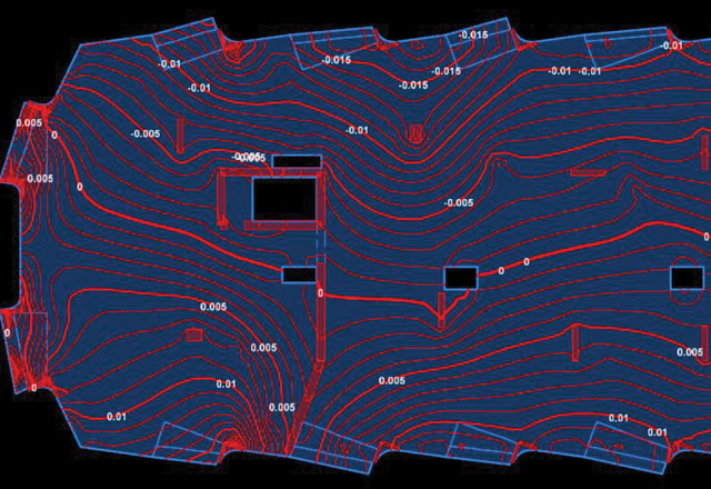
It was a challenge to fit the planned 41 stories within Honolulu’s strict 400-foot height limit. To create a minimum ceiling height of 8’-8” within the typical residential units and considering construction tolerances, the slab depth was restricted to only 7” thick. Unit layouts dictated spans of around 26 feet at the building perimeter, with some localized interior spans of up to 34 feet. The only way to keep deflections at reasonable levels to accommodate architectural floor finish requirements was with post-tensioning. BASE built three-dimensional analysis models of the floors utilizing RAM Concept and went through several iterations of finessing post-tension forces and drapes to optimize the floor for both strength and serviceability requirements.
Expressive Structure as Architecture
The most distinctive features of the building are the beautifully sculpted exterior columns made possible only through extensive collaboration between the architect, structural engineer, and design-assist contractor. Several meetings were convened early in the design process to evaluate an efficient and economical design for the 400-foot-tall columns while still providing an iconic shape for the exterior of the tower that forms an intimate connection to its surroundings.
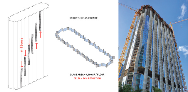
The resulting exterior columns stretch in and out, undulating back and forth as they progress vertically along the façade like the swaying red sugar cane their form was based on. The key to the expressive columns’ structural performance is a central core or stem within the shape where most of the load would be carried. Thinner concrete segments project from that stem, which swell and ebb in unison to provide the columns’ dynamic form. After many studies, the design team arrived at a single central core of constant area and shape at each column that extends through the entire height of the building capable of carrying the tower’s structural loads. This uniform shape allowed for easy lapping/coupling of reinforcement, consistent dimensions for tie and cross-tie fabrication, and a single shape for ease of forming.
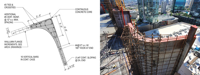
Although, the formwork costs incurred for these columns were higher than conventional columns, the efficiency and simplicity of the concept allowed for easy modularization. The architect produced several sketches and isometrics illustrating the cycling of formwork around the tower footprint, and these depictions reinforced and helped communicate the efficiency of the system so it could be accurately captured by estimators. As a result, pricing exercises revealed that the final column forms resulted in cost savings for the project, both in reduction of initial construction cost as the expressed column concept replaced areas of expensive curtain wall glazing and in long-term operational costs due to reduced energy requirements from lower solar heat gain to the units due to the concrete perimeter enclosure.
Construction Challenges
Determining whether post-tensioning would result in any unsightly shortening of the slab was a unique construction question that needed to be answered. With the prominent architectural columns exposed at the perimeter, movement of these columns inward could produce an unintended alteration to the aesthetics of the carefully sculpted concrete façade. The design and construction team considered many options, including pour strips in two directions and slip joints at the columns. But these options would slow construction and be difficult to execute in the field. In lieu of more intrusive modifications, floor designs were instead further studied and optimized to provide the least post-tensioning required for strength and serviceability to reduce the potential for shortening. While typically not done, the structural engineer developed detailed finite element analysis models to determine movement estimates based on both shortening due to post-tensioning and shrinkage due to curing of the concrete. These estimates were provided to the contractor for their planning of the tower and architectural column construction.
While the custom steel forms chosen for the exterior columns helped create a clean and consistent finish, they prevented the post-tensioning stress pockets from being placed in their normal locations within the columns. Even if there was a way to cut holes in the forms for these pockets, the grout plugs could create some visual discontinuities in the otherwise uniform face of the architectural columns. The rhythm of the exterior columns’ undulating shape meant that the column was at its widest at the slab edge on one side of the building while being at its narrowest at the slab edge on the opposite side. The team took advantage of this feature by anchoring the tendon dead ends on the wider end and locating the tendon live ends to be stressed outside the column footprint on the narrower end. At floor levels where this solution was not feasible due to the column having uniform projecting legs, the structural engineer and contractor coordinated locations for stressing tendons within existing slab openings or provided stressing blockouts. Where tendons were unable to pass through the column core, conventional rebar was lapped with tendons and anchored within the supporting column to satisfy code requirements.
Completion
Planning was a big part of executing the undulating concrete façade. The undulating columns had to be integrated with the exterior window wall, the balcony slab edges, balcony glass railing, and unit interior layouts. Prior to construction, the architect, structural engineer, and contractor developed a full-scale mockup of the exterior column, including vertical and slab reinforcement. This mockup was constructed to help identify constructability issues, evaluate mix designs, confirm the achievement of the desired architectural finish, troubleshoot glazing installation against the sloped column edge, and assess the visual impact of the proposed reveal locations, sizes, and depths. The tower floor plate and each unique column geometry repeats itself every 12 floors, despite appearing random. In addition to the structural concrete façade, over 4,000 window wall panels, including sliding glass doors, of which there are 365 unique sizes, combined with 2,278 balcony glass panels in 111 unique sizes, complete the unique and beautiful exterior of the building.
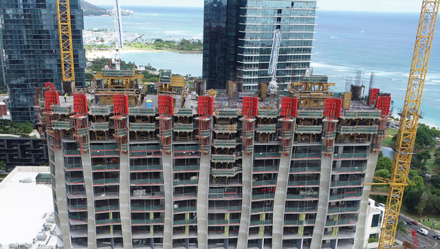
The concrete forming for the tower slabs includes approximately 50 truss flyers and a variety of infill panels, beams and band slab forms for the podium and parking levels. The formwork for the expressed columns includes 22 custom fabricated steel forms featuring multilevel strongbacks to assist with lifting and vertical alignment of the overall system. In all, over 39,000 cubic yards of concrete was poured for the structure’s deep foundations, the architecturally exposed concrete, the structural frame, and a variety of landscaping and pool structures including an extensive concrete planter system helping to beautify two sides of the podium parking levels with a vertical green wall. The structure was reinforced with 6,700,000 pounds of reinforcing steel, both standard strength and high strength where beneficial to reduce quantities and minimize rebar congestion in the higher loaded lower-level columns, concrete columns, and shearwalls. Post-tensioning included 760,000 pounds of 270 ksi unbonded strands, or 0.80 pounds per square foot.
BASE also served as the project’s “Structural Special Inspector” and concrete testing laboratory, logging more than 4,000 hours on the jobsite throughout construction. Construction related services were also provided, including reshoring review, tower crane and man hoist foundations, slab blockouts for concrete pumping. Being involved in these services was found to be beneficial in keeping the project running when questions would arise in the field.
Conclusion
The construction was started in October 2019, just a few months prior to the once-in-a-century worldwide pandemic. With construction considered essential, work was allowed to proceed with a variety of precautions put in place by the contractor. Despite those precautions, work was stopped a few times during construction out of caution for workers’ health and safety. Other challenges included raw material shortages, supply chain issues, and the uncertainty of global logistics. Regardless of these unique challenges, the contractor worked with the owner, design team and trade partners to meet the project’s occupancy date. The tower was topped off within 24 months, in October 2021, and residents started moving in in September 2022.
Despite numerous challenges, the final structure proved to be a success, supporting and expressing the architect’s vision. Additionally, the expressed structure resulted in both economic and environmental benefits, decreasing the amount of glazing required and helping to insulate the tower against the Honolulu sun, reducing air conditioning energy requirements over the life of the building. The result is an iconic structure to serve as a hub for Ward Village’s residents and prominently anchor the development’s central park.■
Project Team
Structural Engineer of Record: BASE
Owner: The Howard Hughes Corporation
Architect of Record: Studio Gang
General Contractor: Hawaiian Dredging Construction Company