
System Description
Using wood structural panels that are required to resist lateral loads and normal wind load requirements of the IBC Section 1609.6.4.4.1, Chapter 30 of ASCE-7, or IRC Section R301.2.1, additional wind uplift resistance from the panel can be achieved by providing additional nails to the shear nailing at the top and bottom of the panel. These additional nails are used to transfer the uplift forces from the top plate to the panel, from panel to panel at splice locations (if present), and from panel to sill plate at the foundation, effectively eliminating the need for uplift straps at these locations. Uplift straps may still be required around window and door openings in exterior walls to transfer the wind uplift loads acting on the header to the foundation below.
Basis of the APA System Report SR-101
- 2015, 2012, and 2009 International Building Code: Sections 104.11, Alternative materials, design and methods of construction and equipment, and 1604.4, Analysis
- 2015, 2012, and 2009 International Residential Code: Sections R104.11, Alternative materials, design and methods of construction and equipment, and R301.1.3, Engineered design
- 2015 ANSI/AWC National Design Specification for Wood Construction (NDS)
- 2010 ASCE/SEI 7-10 Minimum Design Loads for Buildings and Other Structures
- 2015 ANSI/AWC Special Design Provisions for Wind and Seismic (SDPWS)
- 2015 ANSI/AWC Wood Frame Construction Manual (WFCM)
- APA Test Reports, Combined Shear and Uplift Tests on 7⁄16-inch Oriented Strand Board Panels, Combined Shear and Wind Uplift Tests with 10d Common Nails, and Development of Anchor Bolt Spacings for Combined Shear and Uplift Applications
Methodology
Wood structural panel sheathing or siding shall be permitted to simultaneously resist shear and wind uplift loads provided the following conditions are met:

- Panels shall have a minimum thickness of 7/16 Performance Category and may be installed with the strength axis parallel or perpendicular to the studs,
- Anchor bolt spacing shall be in accordance with Table 1, depending on the magnitude of shear and uplift forces,
- 3- × 3- × 0.229-inch steel plate washers shall be used at anchor bolt locations,
- Nails in any single row shall not be spaced closer than 3 inches on center, and
- Nails in any double rows shall be spaced ½ inch between rows.
- Framing anchors and uplift straps that form all parts of the wind uplift resistance system shall be attached to framing on the wood structural panel sheathing side of the exterior walls.
The above conditions effectively eliminate the cross-grain bending as a failure mode in the bottom plate, as shown by full-scale test results. Assuming conditions are met, the following steps may be used to design wood structural panel sheathing or siding to simultaneously resist shear and wind uplift loads.
Step 1 – Design the Shear Walls
The first step in designing for combined shear and wind uplift is to design the shear walls for the structure under the applied wind loads. This method may be used for either the conventional segmented shear wall or perforated shear wall methods. When using the segmented method, a table similar to Table 2 (APA System Report SR-101) can be used to determine the required panel thickness (Performance Category), nail size, and spacing for the individual shear walls. Note that a minimum 7/16 Performance Category wood structural panel sheathing or siding panel must be used.

When using the perforated shear wall method, an additional step is required in the shear wall design. This is the step where the Shear Resistance Adjustment Factor (Co) is used to adjust the Table 2 design values for the geometry of the wall penetrations (see AWC SDPWS). Once the perforated shear wall design is complete, however, the nailing type and schedule information is used in exactly the same way as discussed in Step 3. Information on the perforated shear wall design method is available in Section 4.3 of the AWC SDPWS.
Also, note that wind uplift loads must be distributed around the opening and into the structure below. This may require hardware specifically designed for such applications.
Step 2 – Determine Required Uplift
The required wind uplift at the top of the wall can be found prescriptively by using Table 3, which was taken from the AWC WFCM. Note that the WFCM tables are based on allowable stress design values.

Step 3 – Determine Combined Shear and Uplift Nailing
Based on the nail size and spacing determined in Step 1, find an uplift capacity larger than or equal to the required wind uplift loads determined in Step 2 using Table 4.
Design Examples
A designer wants to use a conventional segmented shear wall segment for combined shear and uplift in a structure being designed for high wind. The shear on the wall segment is determined to be 420 plf, and the uplift along this wall segment is 570 plf. The framing, including bottom plate, is southern pine (G = 0.55) with studs at 16 inches on center.
Step 1 – Design the Shear Walls
From Table 2, using sheathing-grade wood structural panels, a 7/16 Performance Category is selected and attached with 8d nails at 4 inches on center at panel edges and 12 inches on center in the field of the panel. This yields a shear capacity of 490 plf. Note that this value may be increased to 530 plf (see Footnote e to Table 2) because the studs are spaced at 16 inches on center; 530 > 420, therefore OK.
Step 2 – Determine the Required Uplift Force
The uplift force is given as 570 plf.
Step 3 – Determine Combined Shear and Uplift Nailing
From Table 4, based on 8d nails at 4 and 12 inches on center, look for any number that is larger than or equal to 570 plf. There is none. Notice, however, that a double row of nails at 3 inches on center yields a capacity of 540 plf and that Footnote a to Table 4 provides an 8 percent increase for framing with a specific gravity of 0.49 or higher 540 plf × 1.08 = 586 plf. 586 > 570, therefore OK.

The designer should specify a double row of 8d nails at 3 inches on center at top and bottom plates (see Footnote f to Table 4 and Figures 1, 2, 3, and 4), which satisfies the combined shear and uplift requirements for this wall segment. For the shear of 420 plf and uplift of 570 plf, this segment is required to use 5⁄8-inch anchor bolts spaced at 16 inches on center with 3- × 3- × 0.229-inch square steel plate washers from Table 1 8d nails and framing G of 0.50.

Note that the designer must still size the hold-down for the ends of the segmented shear wall based only on the design shear, as is done in shear walls designed for shear only. Similarly, for the perforated shear wall method, hold-downs are required at the ends of the perforated wall and are designed in the same manner as walls without wind uplift. Uplift forces resulting from wind uplift at headers over windows and doors may still have to be resisted by straps or other tie-down devices as when conventionally framed.
Installation Requirements
The installation of wood structural panel walls for resisting combined shear and wind uplift loads shall be as follows:
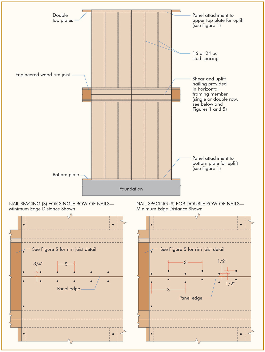
a) Multiple rows of nails applied at panel ends and edges shall be installed in accordance with Figure 1. Panel splice that occurs across studs or horizontal framing such as rim joists shall be installed in accordance with Figure 2.

b) All horizontal joints shall occur over framing or blocking and shall be attached per Figures 2, 3, and 4.

c) On single-story construction, panels shall be attached to bottom plates and top member of the double top plate. Lowest plate shall be attached to foundation with minimum 5⁄8-inch bolts at a specified spacing with 3- × 3- × 0.229-inch steel plate washers, and with minimum embedment of 7 inches or by connectors of sufficient capacity to resist the uplift and shear loads developed in the wood structural panel sheathing or siding walls.
d) On two-story construction, upper panels shall be attached to the top member of the upper double top plate and to rim joist at bottom of panel. The panel edges need not fall in the center of the rim joist. Upper attachment of lower panel shall be made to rim joist and lower attachment made to lowest plate at first-floor framing, which shall be attached to foundation with minimum 5⁄8-inch bolts at a specified spacing with 3- × 3- × 0.229-inch steel plate washers, and minimum embedment of 7 inches or by connectors of sufficient capacity to resist the wind uplift and shear loads developed in the wood structural panel sheathing or siding walls. When a shear and uplift connection is made at a rim joist or with an inter-story splice, the rim joists and/or splice plates must have the ability to withstand the resulting tensile stresses perpendicular to the grain. Since sawn lumber, glulam, and most SCL do not have a published allowable tensile stress perpendicular to the grain, the shear and uplift connection can be made by a wood structural panel splice plate that is sandwiched between the wall sheathing/siding and the rim joist or splice plate. This wood structural panel splice plate must be of the same thickness, grade, and strength axis orientation as the wall sheathing/siding material. This can be seen in Figures 5 and 6. Note that OSB or plywood rim joists are a suitable material for the shear and uplift splice connections shown in Figures 2 through 6.

e) If a wood structural panel splice plate is to be used over a lumber rim joist, due to the potential for shrinkage of the lumber as it dries out, the wood structural panel splice plate shall be cut slightly under height (approximately ¼ inch) to permit room for shrinkage of the rim joist.

f) Where windows and doors interrupt wood structural panel sheathing or siding, framing anchors or connectors shall be used to resist the appropriate wind uplift loads, as required.
g) Roof or upper-level uplift connectors shall be installed on the same side of the wall as the sheathing to prevent twisting of the top plate due to eccentric loading. This may be accomplished by installing the roof-to-wall connectors (hurricane ties) on the outside of the wall beneath the wood structural panel sheathing. It is also possible to install the roof to wall connectors (hurricane ties) on the outside of the wall over the wood structural panel sheathing or to install both the roof to wall connectors (hurricane ties) and top plate to stud connectors on the inside of the wall when the recommendations of connector manufacturers, such as Simpson Strong-Tie, (www.strongtie.com) are followed.
h) When wood structural panels are used and centered over the rim joist, as shown in Figure 3, an engineered wood rim board is recommended for dimension (depth) compatibility with I-joist floor framing and low dimensional changes.
Limitations
Recommendations provided in the APA System Report SR-101 are subject to the following conditions:
a) The structural systems provided in the report shall be designed by a design professional qualified in wood design and installed in accordance with the installation requirements specified in the report.
b) The structural systems shall be constructed with wood structural panels meeting the requirements of DOC PS 1 or PS 2 and trademarked by an approved agency required by the code.
c) The structural systems shall be limited to dry service conditions where the average equilibrium moisture content for solid-sawn lumber is less than 16 percent.
d) The latest copy of APA System Report, Form SR-101 can be downloaded for free from www.apawood.org/resource-library.■
This article was previously published in the February 2015 APA System Report, Form SR-101. It is reprinted with permission.