
Temporary and permanent shoring is often a necessary factor when designing/constructing new building structures in urban areas. The National Council of Structural Engineers Associations’ (NCSEA) Excavation Shoring Design Guide was created and published to aid structural engineers by providing a single source document. The Guide incorporates all the available codes from the federal government and state agencies so engineers can adequately guide the design team and owners to have the most economical project.
To understand shoring and what it entails, one must briefly go back in time and understand why shoring-related work began. In the early history of shoring, most buildings were not complex and usually consisted of perhaps a single story below grade. Construction methods were either open cut and then backfilled or some simple low-level temporary earth retention system. In those days, the project civil engineer acted as the geotechnical engineer, land surveyor, and building engineer and had to design all aspects of the building structure. As technology improved to aid in the design of building structures, and as high-density housing/ multi-story commercial buildings became the norm in urban areas, temporary earth retention systems were required for the following reasons:
- Environmental Concerns
- City Requirements
- Project Cost Viability
- Parking Requirements
- Advances in Below Grade Ventilation Systems
- Advances in Building Structure Modeling
Environmental concerns and city requirements almost always go together (Items 1 and 2 above). As property in urban areas becomes limited due to high demand, all available properties, no matter the below-grade condition, are developed if they comply with all City rules and regulations. Most of these sites are around below-grade city infrastructures, sensitive utilities, and high-ground water tables that are not allowed to be de-watered or on or near contaminated sites. Shoring design needs to become complex to address these issues and concerns.
Soil-cement mixing (SMX), also called deep soil mixing (DSM), was developed in Japan and Europe; SMX finally came to the United States about fifty years ago. It was initially used for ground improvement and levee strengthening; it now has migrated into temporary and permanent shoring applications. SMX has become the most viable option for creating a continuous shoring wall that supports the excavation and provides a hydraulic/contaminate barrier when adequately constructed. SMX columns are installed by injecting and blending cement into the soil using a drill rig equipped with single or multiple augers/paddles or a specialized proprietary cutter head. The soil is mixed with the binder material(s) in situ, forming continuous, overlapping soil-cement columns or a continuous wall of uniform thickness. Steel beams are placed in the soil-cement columns to provide rigidity. The SMX system, combined with steel soldier beams and tiebacks (if allowed), serves to shore the excavation and cut off lateral groundwater flow, thus reducing the amount of de-watering required from within the excavation. Soil-cement walls are considered temporary, and permanent building walls are built inside the soil-cement walls following waterproofing application.
As the technology developed to meet the demand for construction in high-density urban areas, the demand for deeper cuts increased, resulting in the advanced state of the technology available to us today. In the face of the increasing need for highly developed expertise, engineers began to specialize in narrower fields of practice. As a result, a vacuum was created for soil retaining structure design work between the geotechnical engineer and the building structural engineer. Both the geotechnical engineer and the structural engineer believe that designing the temporary earth retaining structure related to the excavation of the building site is not their responsibility. They believe the excavation and shoring work is a means and method for the general contractor to incorporate into their work. As a result, many structural engineers strictly limit their scope of work to the design of the building only, with all other services excluded. In addition, most geotechnical engineers consider the design of retaining structures to be the responsibility of the structural engineer and is not within their field of expertise.
That said, designing soil retaining structures has become a specialized field for a group of engineers who are either working with a specialized shoring contractor or frequently exposed to this kind of work. This article summarizes the big picture of shoring and reviews the different types of analysis for both cantilever and restrained systems. In addition, the Excavation Shoring Design Guide is briefly reviewed for use when designing a shoring system for a building structure with either a single level below grade or multiple levels below grade; here is a checklist of items to consider before starting your initial design.
- Excavation concerns, such as: how deep is the excavation? (Waterproofing concerns? Is a construction slab required? Does the engineer need to account for over-excavation due to poor soil conditions?)
- Understand subsurface stratigraphy.
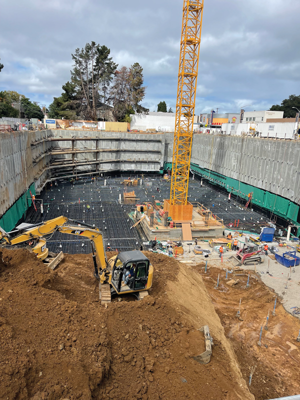
- Groundwater table (secant or non-secant system); refer to Figure 1 for a temporary secant shoring project.
- Is the new building structure a full lot line construction? Does the property allow the temporary shoring system to be installed on the project property?
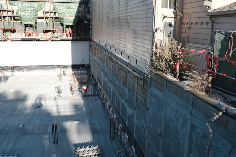
- What type of structures are located around the excavation (trains, existing building structures, and their foundations, etc.)? For example, refer to Figure 2 for underpinning an existing three-story structure and suspending a historic façade required to remain in place.
- What are the existing site utilities (street utilities, public utility easements that may run adjacent to project property)?
- Are you allowed to encroach into the Public Transportation Right-of-Way (ROW)?
- Will you be encroaching into any public transportation zone of influence? Do you need to account for their specific loading requirements?
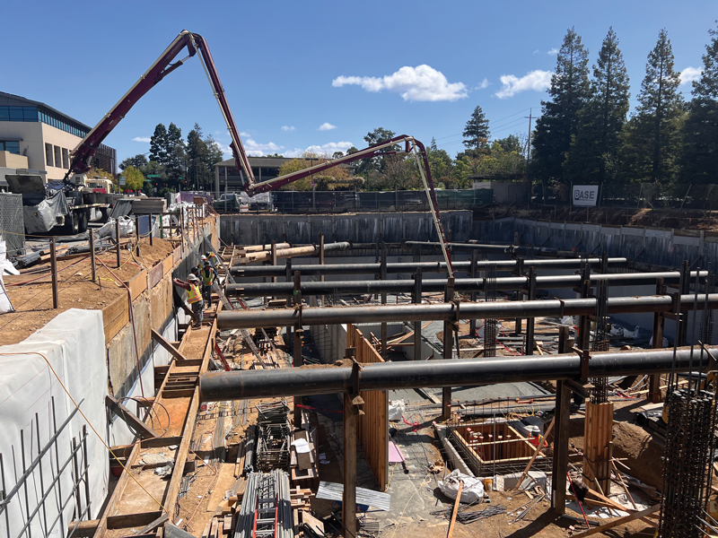
- Understand encroachment agreements of your local or state jurisdiction; are tiebacks allowed? Does the agency charge a fee to install a tieback into the public ROW? Refer to Figure 3 for an internally braced project where tiebacks were not allowed in the public ROW.
- Can you lay back the site? Can excavated material be stored on-site, or does it need to be hauled off-site?
Once the scope of the project is understood, requirements can be established, including all geometry, external loading conditions (temporary and/or permanent, seismic, etc.), performance criteria, encroachment limitations, and construction constraints. The items outlined below are a step-by-step process typically followed for the chosen shoring system:
- Evaluate site subsurface stratigraphy and relevant properties of in-situ soil and rock.
- Evaluate design properties, establish design factors of safety, and select a level of corrosion protection.
- Select lateral earth pressure distribution acting on the back of the wall. Add appropriate water surcharge, traffic/construction surcharge, and seismic pressure and evaluate total lateral pressure. A staged construction analysis may be required for walls constructed in marginal soils.
- Determine if ground anchors can be used or if internal bracing is required.
- Calculate horizontal ground anchor loads and wall bending moments if ground anchors can be utilized. Adjust vertical anchor locations until an optimum wall bending moment distribution is achieved. Determine if ground anchors need to be de-tensioned; if they need to be de-tensioned, they need to be located to minimize the effect on the below-grade structure.
- Evaluate required anchor inclination based on right-of-way limitations, location of appropriate anchoring strata, and location of underground structures.
- Resolve each horizontal anchor load into a vertical force component and a force along the anchor.
- Evaluate the horizontal spacing of anchors based on the wall type. Calculate individual anchor loads.
- Select the type of ground anchor.
- Evaluate the vertical and lateral capacity of the wall below the excavation subgrade. Revise the wall section if necessary.
- Evaluate the internal and external stability of the anchored system. Revise ground anchor geometry if necessary.
- Estimate maximum lateral wall movements and ground surface settlements. Revise the design if necessary.
- Design lagging systems, design-facing drainage systems, and connected devices.
The next step is to review the different types of analysis for both cantilever and restrained shoring systems. For this article, two different types of shoring systems are discussed: A) continuous shoring walls, such as steel sheet piling, and diaphragm walls, which are typically analyzed on a longitudinal per-foot-of-wall (unit) basis for the lateral pressures, and B) Soldier pile and lagging walls which are analyzed differently than continuous shoring walls. Soldier pile and lagging walls are designed over the pile spacing above the bottom of the excavation. They are considered discontinuous below the bottom of the excavation. Therefore, the loading acting on the active and passive sides of the wall for the embedded portion must be constructed to reflect this discontinuity. The effective width of the embedded portion of the soldier pile (for both active and passive loading) can be computed using the Arching Capability Factor per Table 6-1 of the Caltrans Trenching and Shoring Manual; for example, here is a sample calculation of the effective width.
To determine the passive pressure Adjusted Pile Width (APW), use the following equations E1-a through E1-c.
APW = Pile Diameter × Arching Capability Factor (E1-a)
The Arching Capability Factor, AF, is defined below:
For granular soil: Arching Capability Factor = 0.08 φ ≤ 3 (E1-b)
For cohesive soil: Arching Capability Factor = 0.08 φ ≤ 2 (E1-c)
where:
Adjusted Pile Width ≤ pile spacing
φ = internal friction angle of the soil in degrees
For this design example, use φ equal to 28° for sandy lean clay; soil classification type CL. Input the values into the Arching Capability Factor equation E1-c for cohesive soil. The calculated Arching Factor is 2.4.
Arching Capability Factor = 0.08 × φ = 0.08 × 28 = 2.24
Since the number calculated is greater than 2.0, for cohesive soils, use 2.0 to calculate the adjusted pile width.
APW = Pile Dia. × AF = 2′- 0″ × 2 = 4 feet – 0 inches
The calculated adjusted pile width is less than the pile spacing and can be used without further adjustment.
Soldier piles are designed as vertical beams to resist the bending moments and shears resulting from the lateral loads acting on the piles. Also, vertical loading (if any) must be considered.
Analysis of Cantilever Walls
Cantilever walls may be designed using the Simplified method illustrated in Figure 6-3 of the Caltrans Trenching and Shoring Manual. If this method is used, the computed pile embedment depth (D0) must be increased by 20 percent to determine the minimum theoretical pile embedment depth.
Analysis of Restrained Walls
The Free Earth Support Method assumes that the shoring wall is embedded far enough to assure stability. Still, the available passive resistance cannot restrain the shoring wall sufficiently to induce a negative moment in the wall (i.e., there is no reversal of moment below the bottom of excavation). The theoretical pile embedment required for stability is determined by statics. The theoretical depth of embedment needed is determined by summing moments due to all pressures acting on the shoring wall about the point of restraint. The embedment depth is adjusted until the sum of the moments about the point of the restraint is zero. Moments and shears in the shoring wall and the restraint reaction may be computed after determining the embedment depth.
The Fixed Earth Support Method assumes that the shoring wall is embedded sufficiently to provide adequate “fixity” at the pile embedment portion of the shoring wall (i.e., the deflected shape of the shoring wall is such that the wall reverses curvature over its embedded length). Unlike the Free Earth Support Method, moment reversal takes place over the embedded portion of the shoring wall. Compared to the Free Earth Support Method, the pile embedment computed using the Fixed Earth Support Method is longer; however, pile moment demand, pile deflection, and restraint reaction are typically reduced. Using commonly available structural analysis software (i.e., RISA 2-D or 3-D, Tekla Tedds, Microsoft Excel, or any nodal analysis software), determining the depth of embedment required to produce the appropriate deflected shape of the shoring wall is just a matter of iterating the embedment depth.
The calculated pile embedment depths must be compared against the following suggested minimum values for the three different analysis methods described above:
- Cantilever walls: Pile embedment depth shall not be less than the height of the retained cut
- Restrained walls less than 20 feet in height: Pile Embedment depth shall not be less than 6 feet
- Restrained walls equal to or greater than 20 feet in height: Toe depth shall not be less than 8 feet.
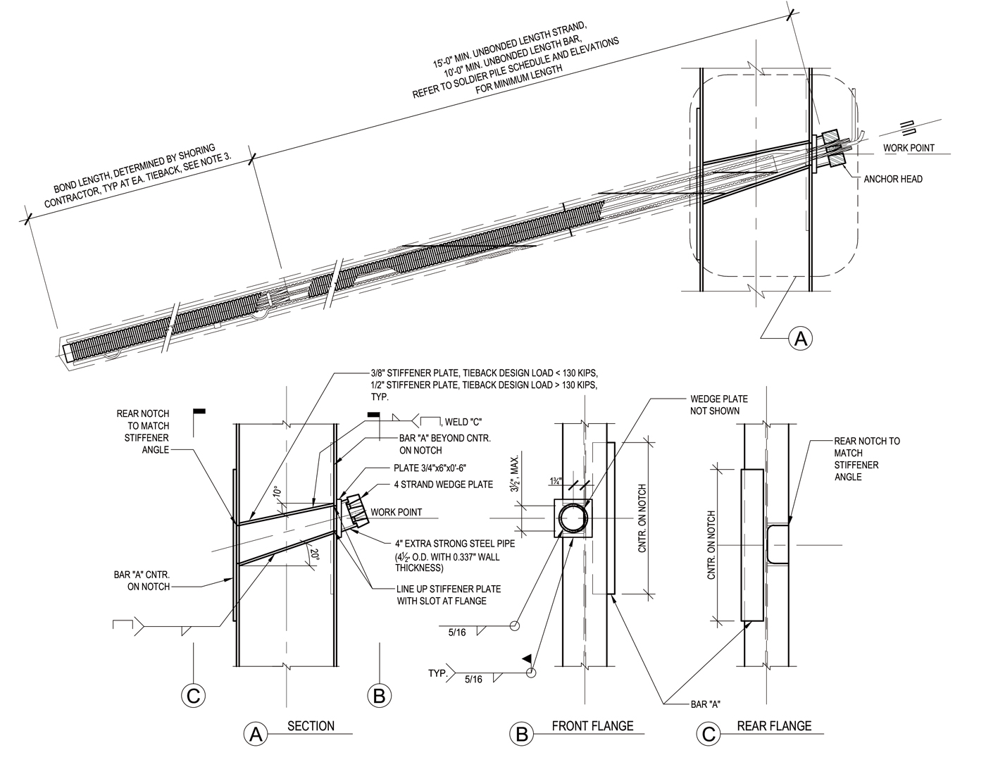
NCSEA’s Excavation Shoring Design Guide provides step-by-step examples covering everything from temporary to permanent cantilever and restrained soldier piles to temporary and permanent soil nail walls. In addition to pile sizing, the Guide covers various lagging systems, provides design provisions for all the primary shoring connections for a restrained approach, and provides real-life construction details. Figure 4 replicates a sample temporary tieback detail from the Guide to aid in construction documents.
To summarize, some major site constraint issues affect shoring design and the significant design steps required to design the temporary or permanent shoring system. The design of temporary or permanent shoring systems can be just as complex as designing the building structure. Therefore, extensive planning and care should be taken to ensure that the most appropriate shoring system is chosen to provide the most economical system to the owner and the most flexibility to the general contractor to build the new building structure. The NCSEA Excavation Shoring Design Guide seeks to help identify those considerations and provides steps for several different design approaches.■