
Using ASCE/SEI 7-22
Designers using the 2022 Edition of the ASCE/SEI standard Minimum Design Loads and Associated Criteria for Buildings and Other Structures (ASCE/SEI 7-22, ASCE, 2022) will find significant changes to the seismic design of diaphragms and their chords and collectors: a new diaphragm design methodology added, an existing methodology expanded, significant changes affecting bare steel deck diaphragms, and more. This leaves the user needing to choose between three methods of diaphragm seismic design and needing to incorporate other updates into their designs. The changes were generated from research and code development efforts that go back years, with contributions from many, including research and guideline development teams and the NEHRP and ASCE 7 update participants. This article provides an overview of these changes to diaphragm seismic design from the designer’s perspective.
Three Methods
The three diaphragm design methods found in ASCE/SEI 7-22 are the traditional design method of Section 12.10.1 and 12.10.2, the Alternative Design Provisions for Diaphragms including Chords and Collectors (alternative design provisions) of Section 12.10.3, and the Alternative Diaphragm Design Provisions for One-Story Structures with Flexible Diaphragms and Rigid Vertical Elements (alternative RWFD design method) of Section 12.10.4. The traditional design method of Section 12.10.1 and 12.10.2 has been used with only minor changes since the 1980s; this was the only diaphragm design method available in building codes until ASCE/SEI 7-16 (ASCE/SEI, 2017). When using the traditional design method, diaphragm design forces are determined based on the seismic design parameters for the vertical elements of the seismic force-resisting system without consideration of the effect of the diaphragm system on the response of the structure. This method is permitted for all structures, except precast concrete diaphragms in Seismic Design Categories (SDCs) C through F.
The alternative design provisions of Section 12.10.3, first introduced in ASCE/SEI 7-16, explicitly recognize and account for the effect of diaphragm ductility and displacement capacity on the diaphragm design forces. This is accomplished by introducing a diaphragm design force reduction factor, Rs. Section 12.10.3 provisions restrict neither the number of stories nor the building configuration; however, diaphragm construction is limited to the diaphragm systems expressly noted within those provisions: Cast-in-place concrete, precast concrete, bare steel deck, concrete-filled steel deck, and wood structural panel diaphragms. The alternative design provisions are mandatory for precast concrete diaphragms in structures assigned to SDC C, D, E, and F. It is optional for all other diaphragm types and SDCs.
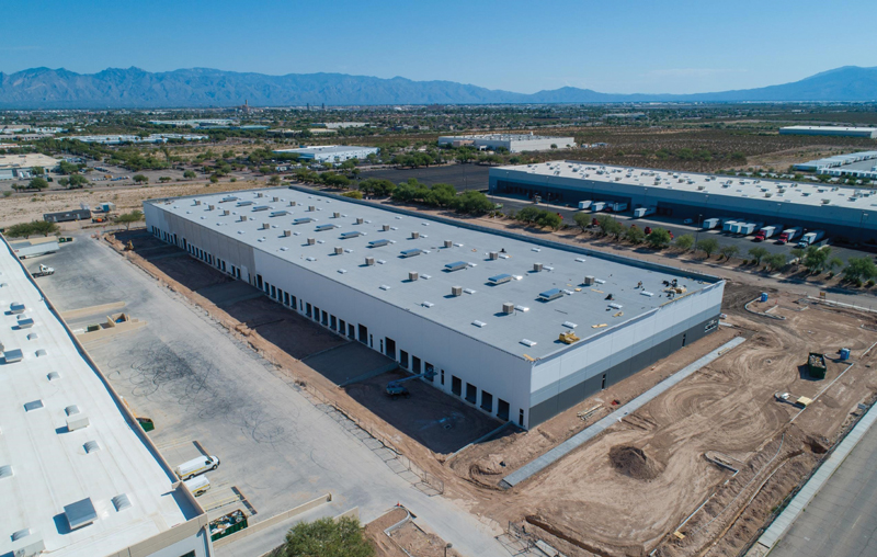
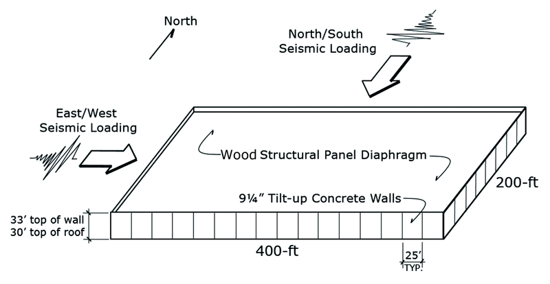
The alternative rigid wall flexible diaphragm (RWFD) design method of Section 12.10.4 introduces diaphragm seismic design provisions for one-story structures combining flexible diaphragms with rigid vertical elements. This seismic design methodology, new to ASCE/SEI 7-22, specifically recognizes that the seismic response of these structures is dominated by the dynamic response of, and inelastic behavior in, the diaphragm. While the most common occurrences of this structure type are the concrete tilt-up and masonry “big-box” buildings (Figure 1), this section’s rigid vertical element terminology recognizes a broader range of vertical elements for which this methodology is permitted to be used. The primary use of Section 12.10.4 provisions is intended for structures with diaphragm spans exceeding 100 feet; however, use for structures with diaphragm spans less than 100 feet is permitted.
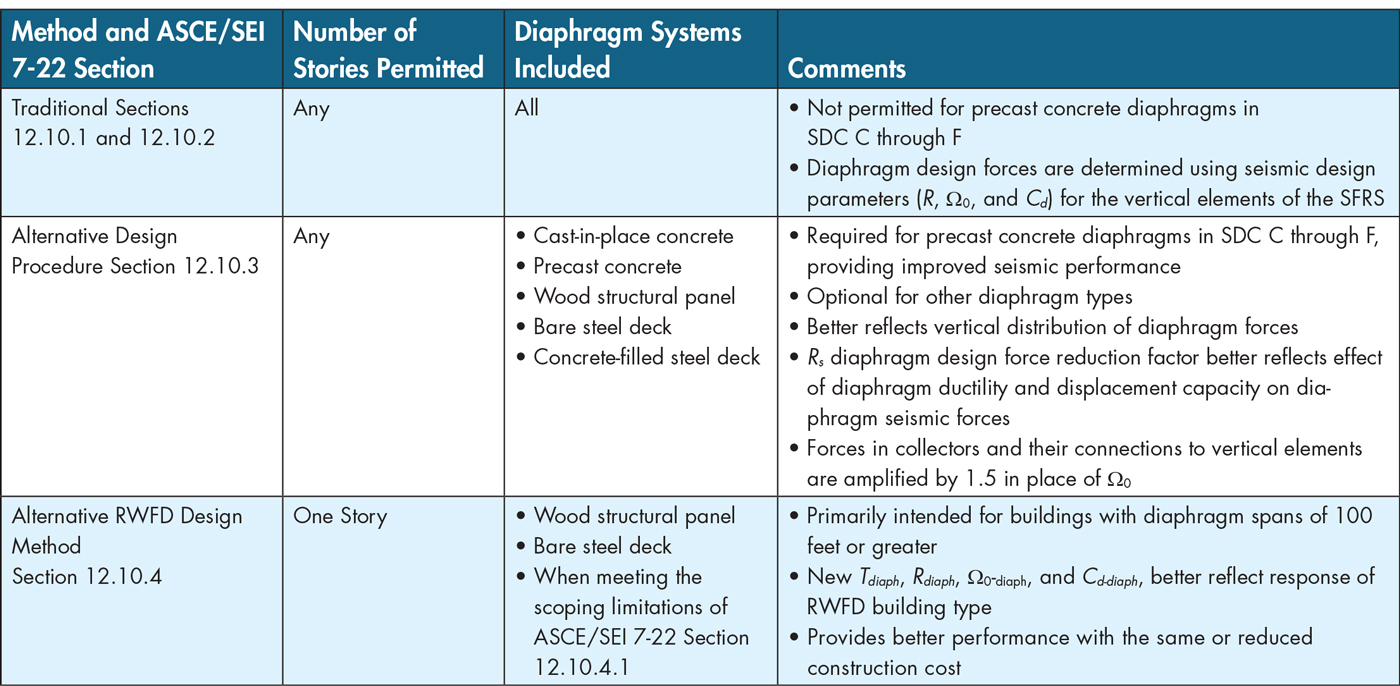
Table 1 provides an overview of the three diaphragm seismic design methods to help the designer choose a method.
Why More Than One Method?
The unifying concept behind both alternative diaphragm design methods is the recognition of the diaphragm system’s influence on the seismic response and performance of the diaphragm and, in some cases, the building. The changes originate from research, including both testing and numerical studies. The new design methods are thought to better reflect diaphragm dynamic response, reflect diaphragm ductility and deformation capacity, and provide better diaphragm performance, sometimes at a lower construction cost. While the traditional design method remains available for most structures, designers are encouraged to use the new methods where applicable.
The alternative design provisions developed out of two distinct efforts. One was a significant multi-university precast concrete research project, Development of a Seismic Design Methodology for Precast Concrete Diaphragms (Fleishman et al., 2013), addressing the alignment of diaphragm seismic forces with diaphragm deformation capacities. This project included significant testing and numerical studies that resulted in redefining the design and detailing of precast concrete diaphragms. Included was the definition of categories of precast connectors based on ductility and seismic design forces appropriate to each category. Concurrently, the Diaphragm Issue Team for the 2015 NEHRP Provisions (FEMA, 2015) worked with collected diaphragm seismic force data from testing and numerical studies to investigate both vertical distribution of diaphragm seismic forces and the influence of diaphragm deformation capacity on the seismic forces. The results of these two efforts were combined in the 2015 NEHRP Provisions and ASCE/SEI 7-16. Two significant steel research projects contributed to the expansion of the alternative design provisions in the 2020 NEHRP Provisions (FEMA, 2021a) and ASCE/SEI 7-22. The Steel Diaphragm Innovation Initiative (www.steeli.org) (Avellaneda et al., 2019; Eatherton et al., 2020; Foroughi et al., 2019; Wei et al., 2019) sought to broadly advance the seismic performance of steel floor and roof diaphragms, while Advancing Seismic Provisions for Steel Diaphragms in Rigid-Wall Flexible-Diaphragm Buildings (Schafer, 2019) also contributed. This research expanded the alternative design provisions to include bare and concrete-topped steel deck diaphragms.
The alternative RWFD design method was developed from a Building Seismic Safety Council building code simplification project that studied code simplification around the design of RWFD buildings. It had long been recognized that code equivalent lateral force (ELF) seismic design forces did not properly reflect the seismic response of this building type. Substantial numerical studies supplementing available building response data (Koliou et al., 2015a, 2015b) led to the development of the new design direction found in Seismic Design of Rigid Wall-Flexible Diaphragm Buildings: An Alternate Procedure (FEMA P-1026, 2015 and 2021). This new methodology was developed into ASCE/SEI 7 design provisions through the efforts of the NEHRP PUC and the ASCE/SEI 7 standard committee. Subsequent work from the project Advancing Seismic Provisions for Steel Diaphragms in Rigid-Wall Flexible-Diaphragm Buildings has expanded the methodology to include bare steel deck diaphragms.
Why Mandatory?
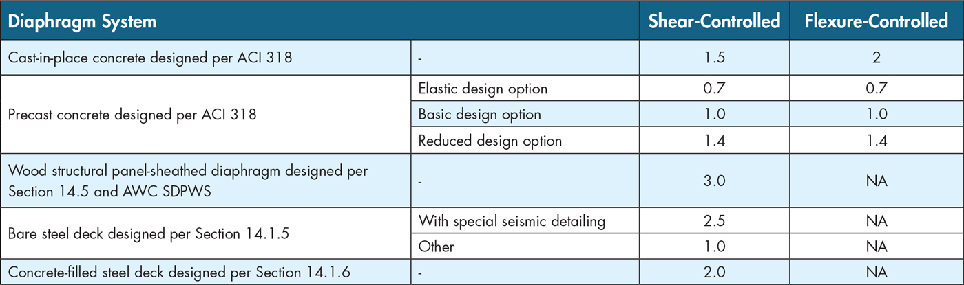
The mandate for the use of Section 12.10.3 for precast diaphragm systems in SDC C through F is based on the research by Fleischman et al., indicating that improved earthquake performance can be attained through recognition of the ductility and deformation capacity based on diaphragm detailing used. Without the Section 12.10.3 provisions for precast diaphragms, the seismic performance might be less than that targeted by the NEHRP Provisions and ASCE/SEI 7. The derivation of seismic design forces when using the alternative design provisions involves dividing near-elastic forces by a diaphragm-design force reduction factor (diaphragm-specific R-factor, Rs). Values for the Rs factor are found in Table 2, differentiated by detailing criteria noted as the Elastic, Basic and Reduced Design Option. The Rs values range from 0.7 to 1.4 at the lower end of tabulated values. Using alternative design provisions will increase precast concrete diaphragm seismic design forces to near-elastic levels, a significant departure from past practice.
Following the development of alternative design provisions and the mandate for use with precast concrete diaphragms, the concrete industry went on to identify a new category of diaphragms constructed with precast concrete elements, designated as “cast-in-place concrete equivalent precast diaphragms,” found in ASCE/SEI 7-22 Section 14.2.2.1. This diaphragm type uses either a non-composite cast-in-place diaphragm over precast sections or a precast diaphragm with cast-in-place closure strips. For this diaphragm type, using the ASCE/SEI 7-22 alternative design provisions is not mandated, allowing the traditional design method of Sections 12.10.1 and 12.10.2 to be used. This is permitted because this diaphragm type does not rely on the connectors studied in the Fleishman research to transfer seismic forces between precast sections.
Concepts Behind the New Methods
The following briefly describes the main concepts behind the two alternative diaphragm design methods. The reader is referred to detailed discussions in the 2015 and 2020 NEHRP Provisions and the commentary to ASCE/SEI 7-16 and ASCE/SEI 7-22.
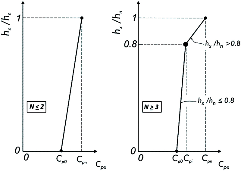
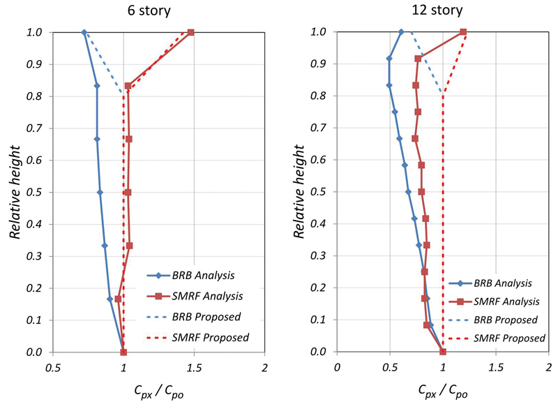
Two primary concepts drive the alternative design provisions. First is the determination and vertical distribution of diaphragm seismic forces based on an assumption of near-elastic diaphragm response. This was driven by a significant body of diaphragm force information collected from testing and numerical studies. Figure 2a illustrates the design acceleration coefficients defining the vertical distribution of diaphragm seismic forces when using the alternative design provisions of Section 12.10.3 of ASCE/SEI 7, and Figure 2b illustrates one of the items of data used to derive the vertical distribution. The second concept is the division of the near-elastic diaphragm forces by an Rs diaphragm design force reduction factor, which reduces the diaphragm forces based on the ductility and deformation capacity of the diaphragm system. These factors also were derived from testing and numerical studies.
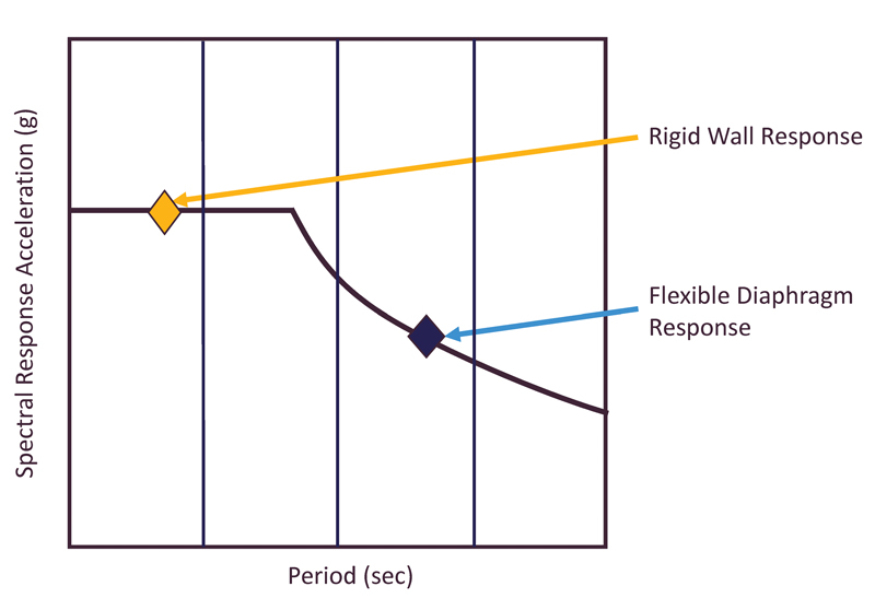
The alternative RWFD method is driven by the long-standing recognition that large footprint budlings with rigid vertical elements and flexible diaphragms have seismic responses driven primarily by the flexible horizontal diaphragm rather than the rigid vertical elements. For the RWFD structure shown in Figure 3a, Figure 3b graphically illustrates that the rigid vertical elements’ seismic response falls at the design spectrum’s plateau. In contrast, the response of the diaphragm falls on the descending curve. The traditional diaphragm design method ignores this behavior, calculating the diaphragm seismic forces as a function of the system used for the rigid vertical elements. The alternative RWFD design method incorporates this known behavior into the diaphragm design provisions.
In addition to developing more realistic seismic design forces, the alternative RWFD provisions incorporate a method of achieving better seismic performance. This is accomplished by designing a boundary zone for amplified shears and reinforces the diaphragm zones alongside the vertical elements where the highest forces and inelastic demands occur. As a result, numerical studies have demonstrated that inelastic behavior will be better distributed through the interior portions of the diaphragm, where the diaphragm fastening is reduced.
Results Vary Between Methods
To date, a limited number of design examples have been developed to illustrate the effect of the alternative design provisions. There are several examples in NEHRP Recommended Seismic Design Provisions: Design Examples, Training Materials, and Flow Charts (FEMA P-2192 V2, 2021). In these examples, diaphragm design forces using the alternative methods are generally the same or less than the traditional method at most building stories but often increased at the top story. One exception is notably increased diaphragm design forces when using the alternative design provisions for bare steel deck diaphragms that do not meet new AISC special seismic detailing provisions.
What Else is Different?
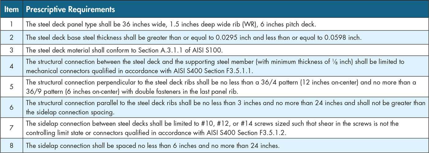
While there are several other diaphragm design changes, one of significance is the addition in AISI S400 Section F3.5.1 (AISI, 2020) of prescriptive and performance-based special seismic detailing requirements for bare steel diaphragms. The prescriptive AISI S400 requirements, provided in Table 3, have been identified through testing to provide good hysteretic response, including retaining post-peak cyclic load capacity. In both alternative diaphragm design methods, the seismic design force for the diaphragm will be significantly affected (by a factor of 2.5 to 3) by the designer’s choice to meet or not meet these AISI requirements.
For More Information
It is recommended that designers interested in further information begin with the extensive commentaries provided with ASCE/SEI 7-16, ASCE/SEI 7-22, and the 2015 NEHRP (FEMA P-1050) and 2020 NEHRP (FEMA P-2082) Provisions. NEHRP Recommended Seismic Design Provisions: Design Examples, Training Materials and Flow Charts (FEMA P-2192 V2, 2021) and Seismic Design of Rigid Wall-Flexible Diaphragm Buildings: An Alternate Procedure (FEMA P-1026, FEMA, 2021) are helpful as well.■
References
AISI, 2020, North American Standard for Seismic Design of Cold-Formed Steel Structural Systems, 2020 Edition, American Iron and Steel Institute, Washington, D.C.
ASCE/SEI, 2017, Minimum Design Load and Associated Criteria for Buildings and Other Structures, 2016 Edition, American Society of Civil Engineers, Reston, Virginia.
ASCE/SEI, 2022, Minimum Design Load and Associated Criteria for Buildings and Other Structures, 2022 Edition, American Society of Civil Engineers, Reston, Virginia.
Avellaneda, R.E., Easterling, W.S., Schafer, B.W., Hajjar, J.F., and Eatherton, M.R., 2019. “Cyclic Testing of Composite Concrete on Metal Deck Diaphragms Undergoing Diagonal Tension Cracking,” 12th Canadian Conference on Earthquake Engineering, Quebec QC, June 17-20.
Eatherton, M.R.; O’Brien, P.E.; and Easterling, W.S. (2020) Examination of Ductility and Seismic Diaphragm Design Force-Reduction Factors for Steel Deck and Composite Diaphragms, Journal of Structural Engineering, Vol. 146, No. 11.
FEMA, 2015, NEHRP Recommended Seismic Provisions for New Buildings and Other Structures, Volume 1 (FEMA P-1050-1), Federal Emergency Management Agency, Washington, D.C.
FEMA, 2021a, NEHRP Recommended Seismic Provisions for New Buildings and Other Structures, Volume 1 (FEMA P-2082), Federal Emergency Management Agency, Washington, D.C.
FEMA, 2021b, Seismic Design of Rigid Wall-Flexible Diaphragm Buildings An Alternative Procedure, Second Edition (FEMA P-1026), Federal Emergency Management Agency, Washington, D.C.
FEMA, 2021c, NEHRP Recommended Seismic Design Provisions: Design Examples, Training Materials and Flow Charts (FEMA P-2192 V2), Federal Emergency Management Agency, Washington, D.C.
Fleischman R.B., Restrepo J.I, Naito C.J., Sause R., Zhang D. and Schoettler M., 2013. “Integrated Analytical and Experimental Research to Develop a New Seismic Design Methodology for Precast Concrete Diaphragms,” ASCE J. Struct. Engr., 139(7), 1192-1204.
Foroughi, H., Wei, G., Torabian, S., Eatherton, M.R., and Schafer, B.W., 2019. “Seismic Demands on Steel Diaphragms for 3D Archetype Buildings with Concentric Braced Frames,” 12th Canadian Conference on Earthquake Engineering, Quebec QC, June 17-20
Koliou, M., Filiatrault, A., Kelly, D., and Lawson, J., 2015a. “Buildings with Rigid Walls and Flexible Diaphragms I: Evaluation of Current U.S. Seismic Provisions,” Journal of Structural Engineering, American Society of Civil Engineers, Reston, VA.
Koliou, M., Filiatrault, A., Kelly, D., and Lawson, J., 2015b. “Buildings with Rigid Walls and Flexible Diaphragms II: Evaluation of a New Seismic Design Approach Based on Distributed Diaphragm Yielding,” Journal of Structural Engineering, American Society of Civil Engineers, Reston, VA.
Schafer, 2019. Research on the Seismic Performance of Rigid Wall Flexible Diaphragm Buildings with Bare Steel Deck Diaphragms, CFSRC Report 2019-2.
Wei, G., Foroughi, H., Torabian, S., Schafer, B.W., and Eatherton, M.R., 2019. “Evaluating Different Diaphragm Design Procedures Using Nonlinear 3D Computational Models,” 12th Canadian Conference on Earthquake Engineering, Quebec QC, June 17-20