
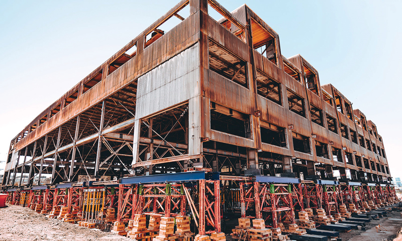
Building 12 at Pier 70 in San Francisco has a long history that continues evolving. The building was originally constructed in 1941 and was used by Bethlehem Steel for shipbuilding in World War II. The building continued to be utilized for the construction of ships after the war and later was used to build the Bay Area Rapid Transit (BART) tunnels that cross under the San Francisco Bay. Unfortunately, in the recent past, the building has been essentially abandoned and fallen into disrepair until this project came to rescue it (Figure 1).
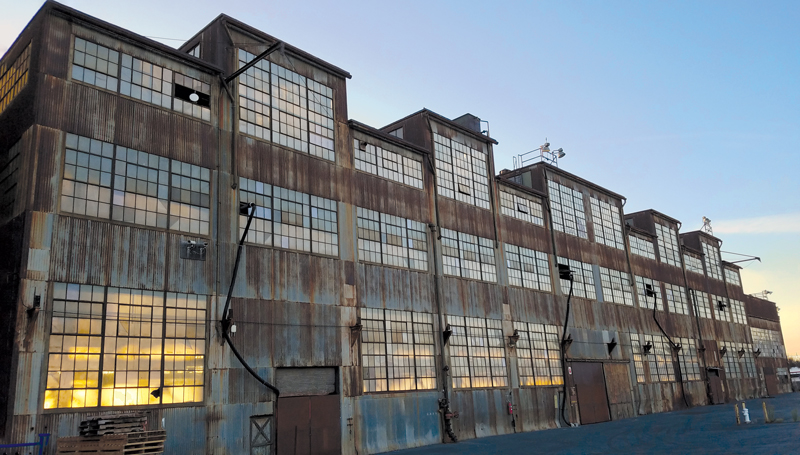
The building is planned to be a retail/maker space in its future life. Shipbuilding designers and drafters were originally located on the upper floor. That floor will now house the designers and makers of wares, and their goods will be sold on the first-floor retail spaces.
The renovation of building 12 is part of a more extensive ongoing redevelopment of the 65-acre pier and surrounding area, including rehabilitating 19 existing buildings and constructing 16 new buildings. This redevelopment will create an entirely new neighborhood in San Francisco and add a waterfront park.
Sea level rise was a concern for a project that significantly extended the lifespan of the building directly adjacent to the bay. The entire site was regraded and raised to combat this issue. To preserve Building 12, it was raised 10 feet to meet the new grade level. Another building on site will be a story shorter after its first floor is buried. Yet another building was moved to a new location.
Degenkolb Engineers was brought on by the general contractor, Plant Construction, to guide the project’s construction planning stage. At the time, Nabih Youssef Associates, SEoR for the building design, was mostly complete with the retrofit design of the existing building superstructure. It was understood that the building had to be lifted, but it was up to the contractor’s team to accomplish it.
Initial thoughts were that new foundations could be constructed offset several feet to the South and East of the existing foundations. The building would be lifted, shifted over, and then set down on the new foundation structure in one process. This would allow the new foundations to be built while the building rested on its original foundations. However, early discussion with lifting contractors determined that, while entirely possible, shifting the building’s location would add significant complexity to the solution. Therefore, the team opted to leave the building in its current location and “just” elevate the building in place. This, in turn, meant that the building had to be held in place on shoring for several months while foundations and basement walls were built.
Since the building would be shored for an extended period, high wind loads were a significant consideration, and a small earthquake was even included as part of the design. Bigge Crane and Rigging was brought on as the lifting subcontractor and designer. Delineation of responsibility was drawn at the base of the existing building. Degenkolb would be responsible for the stability of the existing superstructure, and Bigge was responsible for the design and stability of the shoring system. Column vertical and lateral wind and seismic loads from Degenkolb’s analysis were coordinated with Bigge to design their systems.
Typical shoring systems only support vertical loads, and a separate lateral bracing system is needed. Bigge’s internal engineering team brought an innovative shoring system as part of their approach. Their jacks were incorporated into a 4-leg braced shoring system. Integrating jacks, shores, and bracing in one element meant that separate temporary lateral bracing would not be needed for the shoring. Other systems considered utilized temporary braced frames and other elements that needed to be installed once the lift was complete. This would leave the building vulnerable to lateral loads during the actual lifting and prove costly.
To lift a building is a massive undertaking, and this lift required the 66 columns’ differential movements to be kept within ½ inch throughout the lifting operation. Therefore, hydraulic systems with an integrated computer-controlled monitoring and operations system were selected to keep the building within the tolerances.
Temporary positive connections to the building columns were necessary for the lift. The architect limited connection to the building that would impact the historic patina of the columns as much as feasible. Ultimately, small areas of the columns were cleaned and prepped, and connection plates were welded to the columns to facilitate the lift. The team agreed that, while some irreversible marking was done to the building, these cleaned and ground portions of the column add to the story and history of the building and did not take from it.
Wind loads were not only a concern for the shoring system but also for the building itself. The building was originally designed as a moment frame with fixity at the foundations. Degenkolb analyzed the building in the lifted condition with the fixity removed and found the building would be significantly less stable. Over 5,000 feet of temporary 1-inch cable braces were added around the majority of the building perimeter to add stability back to the superstructure. Cable bracing wrapped around the building columns/beams eliminated the need to weld to the existing structure. This was important in preserving the existing condition of the building and limiting the need to remove lead-based paint from the structure.
The lifting was broken down into 3 major steps: Initial lift, Main Lift, and Set down.
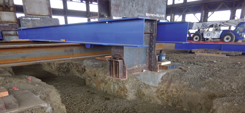
The initial lift took the load off the existing building foundations and brought the building up approximately one-half inch. This allowed for the demolition of the existing building foundations and placement of the new foundations and grade beams. It also kept the building relatively low to the ground, significantly reducing the shoring system’s overturning loads (Figure 2).
During the initial lift, several columns kicked out in plan as they were lifted off their anchor bolts. This was due to trapped loads from the original construction that were restrained by the anchor bolts up until the lift. These movements were typically small and always less than 2 inches. Where they exceeded the one-half-inch horizontal tolerance set out by the SEoR, the columns were winched back into place.
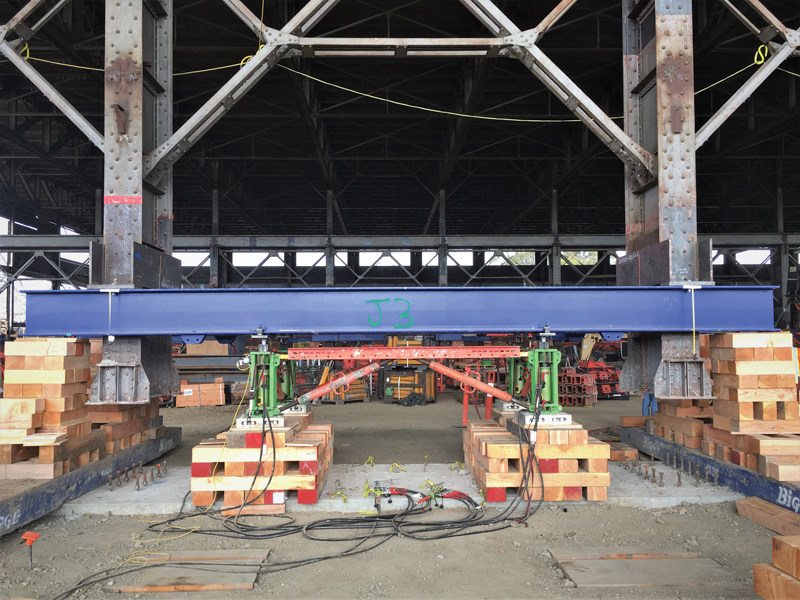
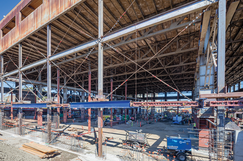
With the new foundations in place, the main lift could occur. First, the shoring/jacking system was installed under the shoring/jacking beams and pushed off the new foundations. The lifting operation proceeded in a rhythmic fashion: the jacks extended to raise the building just enough to install a new 5.5-inch layer of cribbing material at the ends of the jacking beams, then retracted the center jacks to set the building down to allow for the installation of another layer of cribbing under the center jacks (Figure 3).
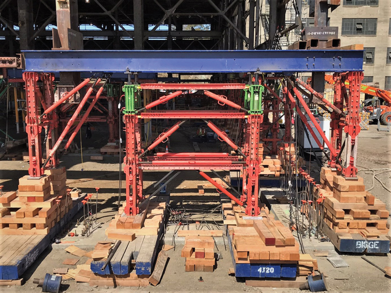
This process continued until the wood cribbing stacks became tall enough to be replaced with new steel shoring ‘modules’ (Figure 4). Then, the process continued in a similar rhythmic fashion until the building was lifted to 11 feet above its original elevation. Throughout the process, immense manpower was needed to install wood cribbing, monitor control points, and install shoring modules at all 66 column locations.
The lifting operation could not have been accomplished without a state-of-the-art computer-controlled hydraulic lifting system that relied on a single brain and three hydraulic hearts to ensure that all one hundred and thirty-six jacks were working in unison. Three Enerpac EVO-Series hydraulic electric pumps – the hearts – were connected to work in unison via one master computer controller – the brain. Each EVO pump consisted of twelve independent hydraulic ports, each feeding the hydraulic fluid to the four jacks of a single jacking/shoring-structure assembly.
Lifting cycles were executed automatically with a push of a button, and the lifting cycles were manually paused, when needed, to perform visual checks and cribbing additions/adjustments, etc., at jacking control points. During a lifting cycle, linear transducers (position sensors) at each jacking/shoring-structure assembly relayed real-time jack-extension measurements to the master controller. The controller used the jack-extension data and the measured hydraulic pressure data at each pump port to confirm that the proper amount of hydraulic fluid was distributed to each jacking control point. This process ensured that all one hundred and thirty-six jacks worked in sync. The master controller displayed the real-time jack-extension and jack-load data for each control point, which the system operator continually monitored.
With the main lift complete (Figure 5), the new steel building columns could be installed below the existing columns. The columns’ splices were welded at the smaller wide flange columns and bolted up to the truss-supporting columns. The bolted connections preserved the original base plate connections so they could be exposed in the finished building. Because the lifting system is a costly rented item and hinders finishing construction, it was requested to determine if the shoring system could be removed once the column extensions were in place but without the first floor constructed. In this condition, the building columns would be two stories tall and only be braced in one direction by the cable bracing. The columns were checked and found to be adequate for the temporary condition (Figure 6).
Without the internally braced shoring modules, lateral wind loads were a significant concern. Therefore, a few negotiated basement walls were cast early to provide adequate temporary lateral resistance. In addition, the lifting beams remained to collect and deliver the lateral loads from the building above to the individual walls below. Once the new basement walls were cast and the new first-floor diaphragm was in place, the building was stable again, and the remaining shoring and bracing were removed.
As noted by the developer, it would have been less costly to demolish the building and build new, but the site’s history would be lost. The authors were happy to be a part of the team, helping preserve the building and bring it new life.■