
A Case Study
Reimagining the iconic Sixth Street Viaduct over the Los Angeles River began with an exhaustive design competition some 10 years ago. By the project’s end this summer, HNTB’s collaborative design approach will have unified and optimized the architecture of a new viaduct while creating a decidedly unique structure in both form and function.
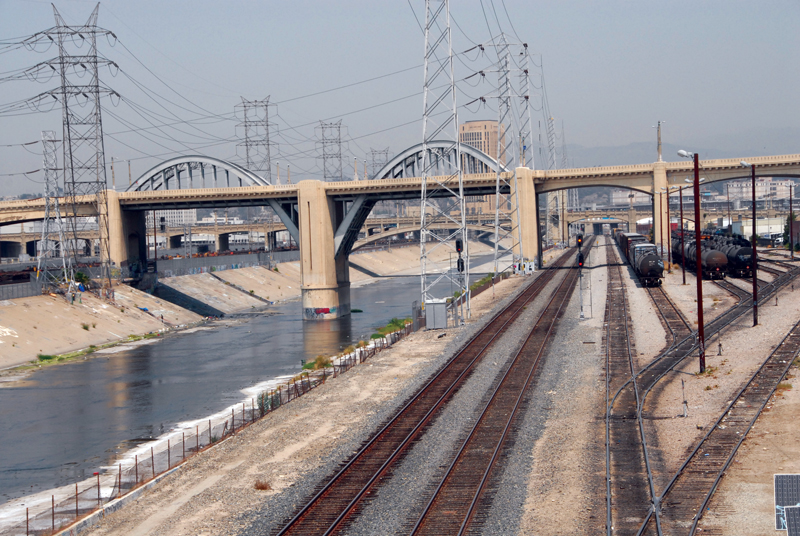
The previous bridge was an emblematic piece of Los Angeles history, as it was the longest and most recognizable of the 12 bridges built over the river between 1923 and 1933. Since its opening in 1932, it has served as a backdrop for dozens of movies, TV shows, music videos, and video games. For these reasons, there was a strong desire to create a replacement structure that was equally impressive and beloved.
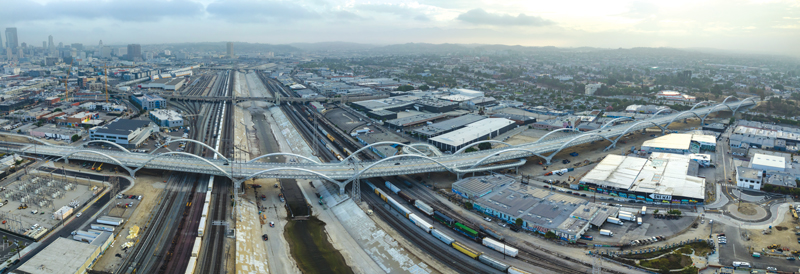
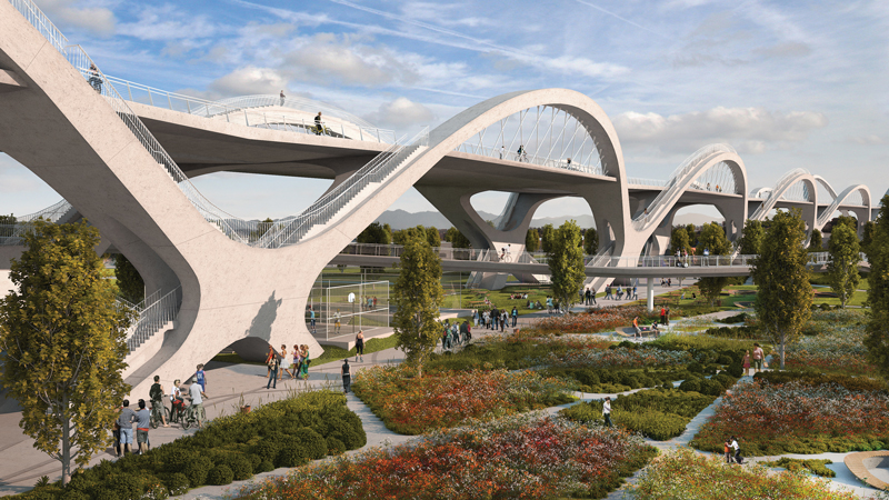
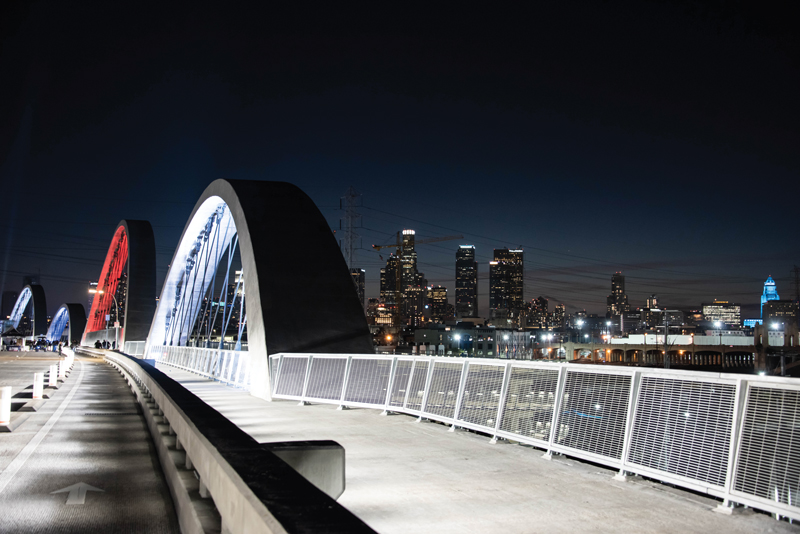
Dubbed the “Ribbon of Light,” the new viaduct continues that tradition in the language of our own time, with its efficient thin profiles made possible by a network of cables that support the bridge deck beneath. The design solution practically achieves the architecture of the viaduct by repetition, creating a striking and memorable bridge structure through the repeated use of concrete network tied arches flowing seamlessly into supporting Y-Bent substructures.
Marrying the architectural vision with the realities of structural engineering was a formidable task. Nevertheless, the Sixth Street Viaduct’s geometry and architectural goals literally dictated the project’s structural approach and led to several innovations.
This article examines the various engineering solutions devised in response to this unique design and the methodologies used to create a sustainable arch and pier system that provides unparalleled resistance to seismic events.
The Bridge’s Evolving Concepts
The ultimate fate of the Sixth Street Viaduct has withstood numerous iterations over the years. Initially, as part of the California Department of Transportation (Caltrans) state-wide effort to improve the seismic safety of the transportation system, plans were made to revamp the bridge after determining it to be seismically vulnerable.
The bridge’s condition, however, was decidedly worse than the other bridges being considered for retrofit – not from seismic vulnerabilities but from the presence of alkali-silica reactive aggregates used during its construction. In layman’s terms, this “concrete cancer” had caused the concrete to deteriorate significantly during its lifespan, making it an impractical candidate for retrofit.
Ultimately, the Los Angeles Bureau of Engineering (BOE), under the leadership of City Engineer Gary Lee Moore, decided to replace the structure and, in 2012, launched an international design competition to ensure that the new bridge was as architecturally iconic as the original. That is when a small group of HNTB engineers and architects, along with representatives of Michael Maltzan Architecture in Los Angeles, convened for a preliminary discussion.
While other designers focused on matching the bridge with a similar signature structure limited to bridging the Los Angeles River, the team took a decidedly different approach. Their vision was to pursue a multi-purpose, multi-modal structure that could be integrated into the surrounding urban environment, extending the signature structure along the full 3,000-foot-plus length of the viaduct. Two potential concepts emerged: a concrete box bridge design clad with art-deco features to help it blend with other historic river crossings and a “stress ribbon” design to float lightly across the urban alignment.
The team initially opted for the stress ribbon, given the design’s innate ability to serve as both a pedestrian bridge and bike path. However, it presented some daunting engineering challenges because it wasn’t practical for the profile grades and stiffness needed in a vehicular bridge.
Later, a larger contingent of HNTB engineers and architects, Michael Maltzan Architecture, and Danish bridge architect Poul Ove Jensen of Dissing+Weitling updated the vision during a three-day workshop, moving away from the stress ribbon concept to a 10-span, concrete tied-arch bridge design. The team determined that the arch form could be more easily manipulated to achieve the desired architectural aesthetics while also giving a respectful nod to the original bridge’s two steel arch spans across the Los Angeles River.
Still, the design of the substructure remained undetermined. One thing was certain – the arch ribs would need to flow continuously down through the deck to the ground to integrate the bridge with the environment below.
Initially, architects favored an X-pier design, whereby each arch rib would continue through the deck. An adjoining arch rib would then continue on the other side, and the two would cross to create the “X.” But there were concerns about the seismic performance of the pier. While such a configuration is not uncommon in buildings where only lateral load is resisted by the X bracing, all of the vertical loadings of the bridge would need to pass through those members.
As an alternative, a Jensen-led team designed a second concept that incorporated a Y-pier substructure. With the Y-pier, the frame would come halfway down and meet at a vertical column configured as a moment-resistant system.
The HNTB design was well received by BOE and an advisory panel of architects, and a unanimous vote subsequently awarded the team the contract.
Engineering Reality Check
Upon contract award, the team continued pursuing the first option – 10 spans of continuous tied arches with X-piers. After more closely studying the concept, however, a reliable seismic system could not be devised, even after considering novel approaches such as a “rocking response” between the legs of the X-piers. While the concept has been considered during seismic retrofits, they determined it was not appropriate for a new structure.
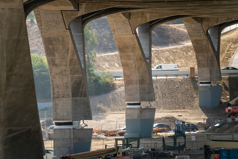
Eventually, the team chose to move forward with the second concept. The Y-Bent design enabled the use of a conventional moment frame in the columns, a more traditional way for bridges to resist seismic forces.
A host of challenges remained, however. At a length exceeding 3,000 feet, the 10 continuous arch spans and nine continuous supporting Y-Bents needed to be interrupted by expansion joints to allow the massive structure to expand and contract. The intermediate expansion joints, although necessary, severely interrupted the sought-after aesthetic continuity of the structure.
Perhaps more concerning, computer models showed the arch ribs above the deck were not responding well, including significant displacements when subjected to seismic ground displacements. This response was aggravated by the aesthetic goal of using unbraced and outward canted arch ribs. Caltrans had sponsored extensive research on the ductility of plastic hinges to dissipate seismic energy in bridge columns. Still, there was scant consensus that this research could be extrapolated to the unbraced and canted arch ribs.
These concerns led to considering seismic isolation, which proved to be a game-changer. However, due to the viaduct’s architecture, the isolators could not be placed on top of the substructure, typical in bridge practice since the arch ribs needed to flow continuously into the Y-pier. The bearings, after all, would have severed continuity between the arch ribs and the upper part of the pier.
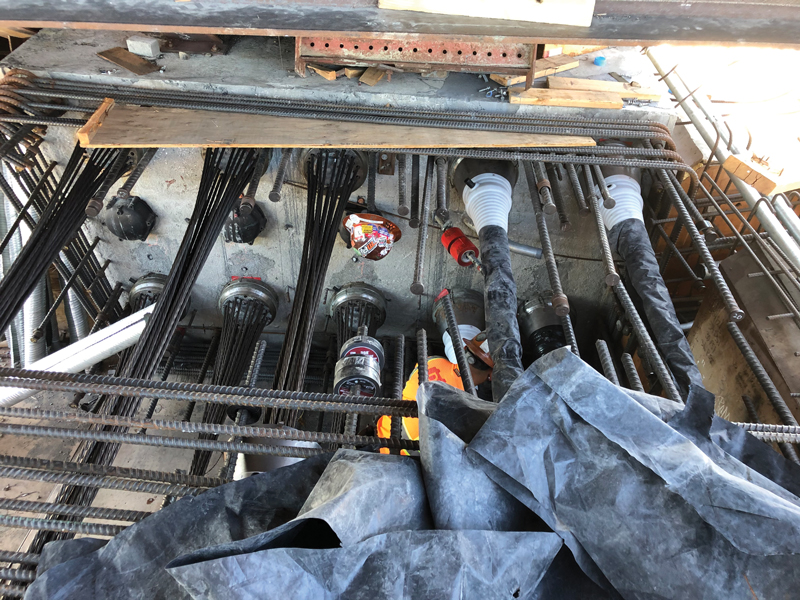
The isolation bearings were placed within the vertical height of the Y-Bent columns. Placing the isolators within the vertical height of the supporting columns is unprecedented for a bridge and led to a fundamental change in the application of seismic isolation by the design team.
Historically, isolation bearings protect a structure from seismic damage and can vastly improve the structure’s functionality after a major seismic event. While the isolators are sized to meet anticipated seismic displacement demands, no provisions are required by guide specifications to protect the bearings themselves from seismic demands exceeding the anticipated earthquake. While potentially helpful, conservatively increasing the displacement capacity of the bearings is not a rational approach if the risks are not fully understood.
The approach chosen was to reconfigure the isolated system so that if seismic displacement demands on the bearings are ever exceeded, the bearing stiffens rapidly with a corresponding increase in lateral restraint. This required that the structure share attributes of a conventionally designed non-isolated structure with ductile seismic hinges added that are only activated after a predetermined displacement within the isolator is exceeded. This “belt and suspender” system with a backup ductile system makes bearing failure and/or unseating within the column virtually impossible.
Next, various approaches were considered for the backup system. In finding the optimal location, the team first considered placing the ductile seismic hinge at the top of the Y-piers, situated at the bottom of the superstructure, to follow conventional construction.
However, in verifying ductility during a pushover analysis, high torsion was observed in the arms of the piers. And once the hinge formed, torsion continued to increase and therefore was not a case of equilibrium torsion. Since increasing torsion could not be tolerated in a ductile seismic hinge, the design team ultimately decided to place the contingency hinge within the 10-foot-diameter drilled shafts that support the structure. The circular section has excellent ductility due to good confinement details and low axial load ratios.
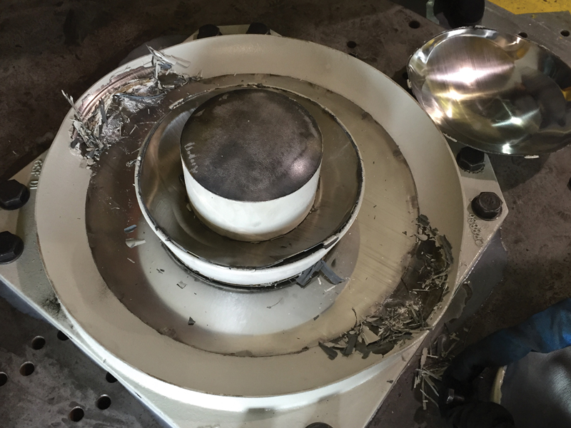
The project uses triple-pendulum isolation bearings manufactured by Earthquake Protection Systems (EPS) in Vallejo, California. EPS invented the original single pendulum bearings in 1986, followed by the triple pendulum bearing in 2006. Over the years, these bearings have been supplied for bridges and buildings worldwide in high-seismic areas.
This new isolation concept would essentially eliminate the possibility of bearing failure and substantially increase the reliability of their bearings, regardless of the level of ground shaking assumed during design.
After much prototype testing, the triple-pendulum bearings were modified to provide a dual radius on the outer slider of the triple-pendulum bearing and modified the inner slider to transition between the two radii smoothly. As a result, the modified bearings manufactured for Sixth Street have the highest lateral strength to vertical load ratio (approximately 55%) ever manufactured by EPS. For comparison, at the 1,000-year-level seismic design event bearing displacements, lateral bearing forces transmitted to the substructure vary between 15% and 20% of the vertical load.
EPS also performed a FEMA P695, Quantification of Building Seismic Performance Factors, analysis against bearing failure and determined the reliability against collapse to be 99.99%, by far the highest of any of bearings furnished for past projects.
Testing Ground for Innovation
The Sixth Street Viaduct project was a hotbed of innovation. When the team determined that the Y-Bents would require strengthening to protect against hinging in the drilled shaft component of the secondary system, it suggested increasing the strength of the reinforcement from grade 60 to 80. This would provide an economical way to comply with the increased strength of the isolation bearings after stiffening without requiring an increase in the reinforcement content of the Y-Bent or the component sizes.
Although Caltrans was in the process of evaluating the general use of grade 80 reinforcement in both ductile members and capacity-protected elements, research was still incomplete. Recognizing the requested use was for a secondary system that likely would not be activated, HNTB sought an exemption for the use of grade 80 reinforcement in capacity-protected members that would not be used for plastic hinging in the secondary system. Caltrans concurred and granted the request.
The use of seismic isolation provided another significant advantage. Since the isolation bearings severed the viaduct from ground constraint, all intermediate expansion joints could be removed, and the viaduct made continuous over its entire 3,060-foot length. However, due to practical construction sequencing limitations, including post-tensioning stressing length limitations, the viaduct needed to be constructed in discrete frames with closure pours used to provide final connections between frames.
As a tied arch, each edge girder of the viaduct is particularly important since the edge girders resist the axial thrust of the 10 continuous arches. The arms of the Y-Bents also require a tension restraint, with the thrust between opposing arms actually exceeding the arch thrust. The project’s prestressing systems specialist, DYWIDAG International, suggested using post-tensioned couplers to join the 10 4.5-inch-diameter edge girder tendons continuing between sequencing frames. Although DYWIDAG could not reference a project where these couplers have been used in the U.S., they had previously developed, tested, and gained approval for their use on several European projects. After discussions with Caltrans, the team chose to use the couplers at each edge girder frame joint following verification testing.
With full continuity of the superstructure achieved, expansion joints were only required at each abutment. The team specified a low-maintenance seismic expansion plate joint still under development by Caltrans at the time. Intermediate expansion joints are always a maintenance concern, so limiting expansion joints to each end of the viaduct and using Caltrans’ developed low maintenance seismic steel plate type expansion joint minimizes the required long-term maintenance of the structure.

Other project details were born from a need for sustainability and structural longevity. For example, the team specified post-tensioned floor beams in the transverse direction, resulting in post-tensioning of the structure in two directions. That, coupled with a low-shrinkage concrete mix for the superstructure, will ultimately reduce cracking and enhance the structure’s service life. The deck concrete also included a fiber-reinforced concrete mix.
Additional service life enhancements include hot-dipped galvanizing of all structural steel and bridge railings. Arch hangers are further protected with a zinc-aluminum alloy coating and a lubricating and blocking compound applied during stranding. All these measures reduce maintenance costs and increase the lifespan of the structure.
Once operational in the summer of 2022, the new Sixth Street Viaduct will be an aesthetically iconic structure in the heart of Los Angeles and a noteworthy and seismically sound addition to the city’s infrastructure landscape. There are high expectations that the replacement viaduct will represent the city for the next 100 years as a recognized icon and new backdrop for its bustling film and music industry.■