
Continuing our series on automation – December 2021 (Installment 1), March 2022 (2), June 2022 (3) – I sat down (virtually) in April 2022 with two more industry experts in digital design: Steve Reichwein, a Senior Associate at Severud Associates Consulting Engineers, and Carlos de Oliveira, a founder of Cast Connex. Below are highlights from our discussion.
You both gave an excellent presentation to SEAoNY back in January about the Madison Square Garden Sphere at the Venetian in Las Vegas. As an introduction for the STRUCTURE magazine audience, could you provide an overview of that project and how parametric design and other digital tools were used in the design and fabrication?

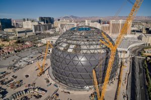
Steve Reichwein: The project is an 18,000- to 20,000-person capacity entertainment venue that will mainly be used for concerts, E-sports, and immersive events. The media plane is the project’s focus: that’s the inside LED screen comprised of over 45,000 LED tiles or over 200,000 square feet of surface area. The media plane is a rather interesting structure that is not ground-supported, except at the back, where there’s a large portal opening for the proscenium. The rest of it is hung from a 440-foot-diameter dome roof that is essentially the roof of the venue. About 12 feet from the venue structure is the sphere that everybody will see from the outside: the 520-foot-diameter geodesic sphere. It’s not a complete sphere; it is cut off roughly 100 feet below the equator at ground, but it goes up roughly 375 feet above ground through the apex. That portion will also be wrapped in an LED video system. The trellis system has about 25 miles of curved steel pipe. While the main structure is not curved, it is segmented at each node. And then there are almost 760 miles of LED strands. So it’s a crazy amount of electronics and structure tied to that external geosphere primary structure.
Carlos de Oliveira: Cast Connex engineered and supplied cast steel nodes for both the exoskeletal geodesic structure on the outside of the venue and the structural backup for the “immersive surface media plane” on the inside. On the outside, you have a spherical structure; on the inside, it is actually a slightly elongated spheroid. But both structures use cast steel nodes at the intersections of the primary structural members. The geosphere is rationalized with latitudes with diagonals that intersect, creating a diagrid with six members framing into each node. Near the top, where Severud undertook additional rationalization to reduce piece count, we have some nodes that accommodate up to 8 members framing into them.
Our first step in designing the casting is to understand the geometric repetition that the structure offers. On the outside, given the nature of how the structure was rationalized, all of the nodes around each of the latitudes are geometrically identical. Once we establish the kind of structural rhythm of that geometry, we can use parametric design in our process to help us build the three-dimensional models of each one of the nodes. And then, with force information provided by the Structural Engineer of Record, we can optimize the castings. So we start with a solid shape of material. Then we look at where the stresses are in that material and start pulling away material where it’s not necessary, and then we optimize the nodes for just the structural loading that is applied to them. We, of course, have to consider how we manufacture those components – how the liquid metal will freeze inside the molds that will produce this component – and so, frequently, we have to add a little more material back to make the component more castable. We try to shape the part to promote what we call directional solidification. The liquid metal will start to freeze at the extremities. That solidification front will propagate towards the heavier sections of the part, and that’s where we will connect liquid metal reservoirs to the casting. Thus our design process is driven first by structural geometry and loading and then by manufacturing constraints.
How much of that decision-making to add and remove material can you teach the computer to do, versus how much must be the engineer steering things hands-on?
Carlos de Oliveira: Well, we’re not there yet in our process. We are not nearly as automated as Steve can get with his parametric design. But the first step might be topology optimization, where we start with a design space and apply the loading to it. We can see areas that are not highly stressed and remove unnecessary material. That process can be relatively automated. However, the output of that process may not result in a particularly useful shape from a practical perspective. For example, material may be missing to keep water or debris from collecting inside the connections. So you end up building back material from that perspective. And then, of course, we must consider manufacturability.
I see many parallels with the design side. Like how you can teach the computer to automate to a certain degree, but then there are the common-sense human things you still have to do yourself. Do you envision the process getting more automated sometime in the future?
Carlos de Oliveira: I think that there is an opportunity for it. All the steps in our design process are types of analyses, and we currently use different software packages to carry out each step. For example, the solidification analysis is happening in software called Magmasoft. And our stress analysis is occurring in a piece of software called Hyperworks. And our 3-D modeling and shaping of the part are happening in SolidWorks. Unfortunately, we’re not yet tying them together nearly as well as possible, and iteration is somewhat manual. If we’re going to get closer to automation in our processes, we have to be able to tie those pieces of software together in a much better fashion, more like how Steve can do with all of the pieces of software that he uses.
Steve Reichwein: Let’s start with the geosphere because that’s more or less the easy one. Basically, we have a sphere with certain loads applied to it – gravity, wind, seismic, and so forth. So when all the superimposed loads are your constants as well as the size, shape, and support conditions, your variables are endless. We started by using algorithmic tools and Grasshopper components, such as Ladybug, Lunchbox, or Kangaroo, to mesh the sphere into equilateral triangles closer to Bucky’s (Sir Buckminster Fuller’s) traditional sphere. Because it is clearly the most optimized in terms of weight, we started there as a base point. But then, after getting Carlos and W&W [the steel subcontractor] involved early in the process, we started to clearly see that there were going to be issues with that type of sphere. First, given the geometric complexities and lack of continuous rings needed to stabilize the structure in phases, it would need a significant amount of shoring. Second, there was repetition in node connectivity and member length. However, you would have a node down near the base that matched a node all the way at the top, but the loading was totally different, so there was no repetition in structural demand. We started to see those pitfalls very early in the process, and we rethought our design of the geosphere completely. We changed the sphere from a traditional icosahedron-based “Bucky” sphere to a “polar geosphere”; it’s essentially a series of continuous, flat latitudes forming complete, elevated rings bisected by 64 diagonals forming a triangularized grid shell from top to bottom. We also focused on congestion elimination for the apex, which was a huge savings. The final scheme weighed more than the base scheme, but we used input from W&W to compare the structural schemes’ actual costs; the polar geosphere turned out to be approximately 25% less cost when all factors were considered. And then, a similar exercise was done for the Dome roof. If we had used the rules of thumb from old steel journals, we would have had 1,000 extra tons of steel in the Dome roof.
Overall, the computational optimizations, simulations, and goal-finding saved the project tremendous material weight and money. We plugged our algorithm into AWS supercomputing and other cloud computing to speed up simulations and decrease the computing time. They were like 2-hour runs that would eventually converge, but it would run a million different schemes. Given that amount of data, we would hone in on the global minima in terms of weight and cost. However, the human element of experience and engineering judgment is critical in this stage. You must have the experience to weed out some of the outrageous simulations. Seeing the results in stages may also warrant some tweaking to the AI, which can help automatically weed out “bad” results for future runs.
Would you say steel is the structural material that lends itself best to design automation?
Steve Reichwein: No, I don’t necessarily agree with that. Both steel and concrete can be optimized individually for material weight and compared against each other using cost. I actually have an algorithm I use for tower studies early on that optimizes and compares steel structures versus concrete structures; cost is the ultimate equalizer for both. We use a structural analysis plug-in called Karamba, made by an Austrian engineer (Clemens Preisinger in conjunction with Bollinger–Grohmann). We’ve actually piloted and gone back and forth with the developer directly to give input and develop the program further. It has an excellent optimization tool for concrete where you can essentially do a shear wall core, run it in the optimization, which uses virtual work, and gives you optimized thicknesses of each piece of mesh for the entire tower in less than a minute. It’s super quick. As far as laying out the core, it won’t help you with that, but you can build AI programming into the layout or start with the traditional topographical analysis and figure out roughly how big your cores should be. Additionally, the architect may have some constraints on the core layout that gets built into the algorithm.
It takes longer to do the concrete optimization because you’re using finite element shells, where there are so many more elements as opposed to steel structure, which is comprised of stick elements. But there are cloud computing opportunities, as well as cloud-based plug-ins. So you can plug them directly in Grasshopper, and it will run certain nodes with cloud-based supercomputing.
Have you let architects play around with those tools, in between calls to the structural engineer?
Steve Reichwein: Yes. We worked with Shapedriver a little to make some tools that architects could just plug in height. It was a simple box that didn’t get very complicated, but it was basically our tower optimization algorithm dumped into a Cloud-based computing service; then, you can share that with anybody. It’s all cloud-based, so the client will just need a link to access it, and then they plug in the variables and run the program in literally seconds. It’s very quick.
Carlos de Oliveira: It’s interesting when you think about how we do topology optimization as we start with a design space to which we apply loading. Then we look at the lowest stressed material, which gets eaten away from our models. In contrast, you can compare that with the way that you might approach a steel-framed structure like the MSG Sphere’s geosphere, for example, where you start with a preconceived structural approach and then use the algorithms to optimize several specific parameters simultaneously – like the number of latitudes and the number of nodes at each latitude. In this approach, you go directly to more buildable solutions, whereas topology optimization requires more post-processing to develop a useful solution.
It seems like some parts of the construction side are already quietly implementing automation tools. Can you give any examples?
Steve Reichwein: Connections, in general, are getting fairly automated. Q-nect will run an algorithm on your entire structural steel building if you give them loads and geometry. They basically just need a Revit model with parameterized beam end reactions, and it will design all the connections and detail them, all in about an hour. Ridiculously fast. That’s built on tools commonly available now through Grasshopper and Dynamo, where you could do something similar yourself or bring in Q-nect as part of the team.
Carlos de Oliveira: Not recently, but it reminds me of when shops moved towards plasma-cut plate CN files to try and make optimal use of plate material to cut as many pieces out of one big piece as you can, so you nest them. Now there are even automated weld fitting machines. Really modern steel fabrication shops just don’t look anything like fabrication shops of old.
Do you think robots will take all our jobs someday?
Carlos de Oliveira: The best structural engineers and the best architects are the creative ones. The most striking architecture, the most interesting buildings, speak to us on a human level. I don’t think computer code can create the places, buildings, communities, and cities we want to live in. So, although parts of our profession have been automated, and more and more will be automated, I think an essential aspect of our profession can never be automated: the creativity and the human aspect of what we do.■
Many thanks to Steve and Carlos for sharing information about the project and their insights on these trends in our industry.