
Reinforced concrete is a construction material widely used in many applications, including buildings, bridges, and other infrastructures. Due to its massive size and various redundancies, concrete structures are often considered solid, robust, and safe. However, there have been instances of concrete structure failures and collapses, many due to erroneous assumptions or oversight by the designers in evaluating the design situation or poor construction practices. This article highlights several design and construction situations that designers and builders should pay special attention to in order to prevent failures.
Design of Silos
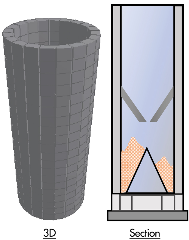
Silo structures are notoriously known to many as a structure requiring special attention, not because of the external loads, such as wind or seismic, but due to the storage load of the bulk solid. The unwary designer might unrealistically simplify and assume the load to be hydrostatic pressure caused by a fluid, even though the actual storage material might be solid granular material or particulate in nature. The force exerted by particulate materials onto a silo container can be different. First, the designer must consider conditions during the filling up of the silo and discharging of the materials. There might be instances of eccentric loads (Figure 1) and higher loads (e.g., impact) caused by these processes. Next, there must be consideration of whether the presence of moisture, gas pressure, or other ancillary equipment imposes additional loads. For example, some grains are known to absorb moisture and cause additional loads due to swelling of the grains. This example illustrates the importance of determining as accurately as possible the type of loadings exerted by different materials onto a structure, including loading magnitude, direction, and possible permutations in area. Detailing a concrete silo with a single layer of reinforcement to deal with hoop tension only by assuming symmetric loadings would clearly be inadequate.
Effective Width of Support Member
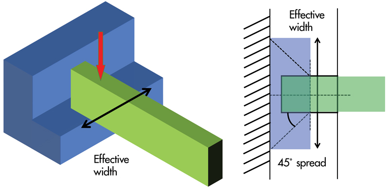
Consider a case of a concrete support structure with a wide corbel (or nib) to catch an incoming beam (Figure 2). Due to its short length compared to its depth, the design of the corbel should not be based on a bending formula. Instead, a strut-and-tie model would be more appropriate to work out the necessary reinforcements to resist the load. However, there is still a need to work out the effective width of the corbel used in resisting the load and not assume the entire width of the corbel can be used. To work out the effective width, designers can refer to guidance on effective slab width at exterior slab-to-column connections, where a 45-degree spread from the centerline of the column is recommended. There may be a larger angle of spread if the transverse stiffness of the corbel is high, making it very rigid (e.g., thicker section or higher reinforcement ratio). But an overestimate of the effective width might give rise to over-prediction of capacity and result in design deficiency of this critical structural element. Under-design of such low redundancy structural elements (e.g., cantilevers, simply supported beams) can be very dangerous because there is no alternative load path for redistribution, and failure is often likely to occur. Therefore, correctly selecting the effective width can be a crucial design aspect.
Nib Failure
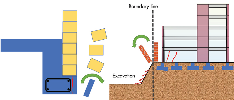
One common way to support a brick wall façade is by designing a nib. Because of the small bearing length of the nib, it is necessary to place the reinforcements precisely. This ensures that sufficient bearing length of the nib is reinforced with reinforcement bars. Suppose the reinforcement bars were placed short, resulting in extra concrete cover, or worse, using additional thicker plaster to achieve the required length. In that case (Figure 3), the unreinforced portion of the nib can easily be dislodged under the weight of the bricks. This example highlights the dangers of having extra concrete cover and failure in the unreinforced zones in a structural member, especially when such unreinforced zones are required to support heavy loadings.
Cracks at Joints and Discontinuities
In concrete structures, high stress concentrations can occur in regions such as turnings and kinks (e.g., connecting truss members and inclined members, Figure 4. In addition to correctly identifying the type of actions to be resisted (i.e., axial, shear, bending, and torsion) by a particular structural member, it is necessary to detail the reinforcement bars correctly. Members that are not strictly beams (dominantly bending and shear) or columns (dominantly axial load) could potentially be subjected to a combination of more than one dominant action. The detailing process can become difficult due to awkward geometry and difficulty fitting bent bars in tight spaces, which may sometimes result in extra concrete cover that may not necessarily be desirable and could sometimes result in cracking.
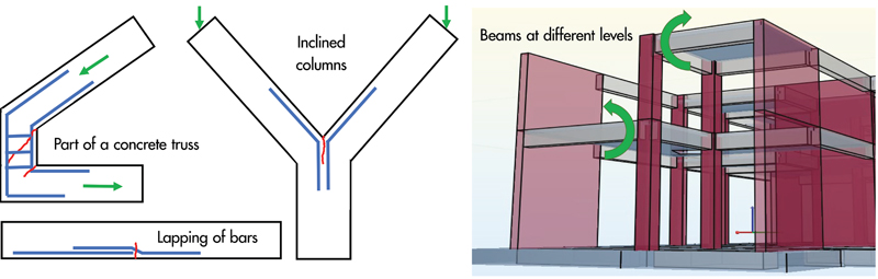
Splicing of reinforcing bars (especially if spliced all in one location) may introduce a weakness at the location of bar discontinuity. When bars need to be discontinuous, splicing should be staggered and preferably avoid highly stressed regions. Another design situation requiring attention is beams framing into columns at different levels on opposite sides. Designers should know that the opposite direction moments do not equalize and design for the actions imposed by such a configuration. This can be a more common issue in concrete construction, where there is often some fixity at the joints.
Flat Slabs to Span Full Load in Two Directions
When designing a flat slab system (Figure 5), designers need to note that the full load must be taken in the two orthogonal directions independently. Some designers mistakenly assume the flat slab system behaves similarly to a two-way spanning slab and underestimate the loading and bending moments, resulting in inadequate reinforcements. They might have distributed the full load in two directions (each direction taking one half) or designed for the full load in one direction but totally missed out the orthogonal direction. This misconception could have come from designing a one-way spanning slab where only one direction of spanning (the shorter span) of the slab is required. The other direction is also taking the full load but in the form of the beam and not the slab.
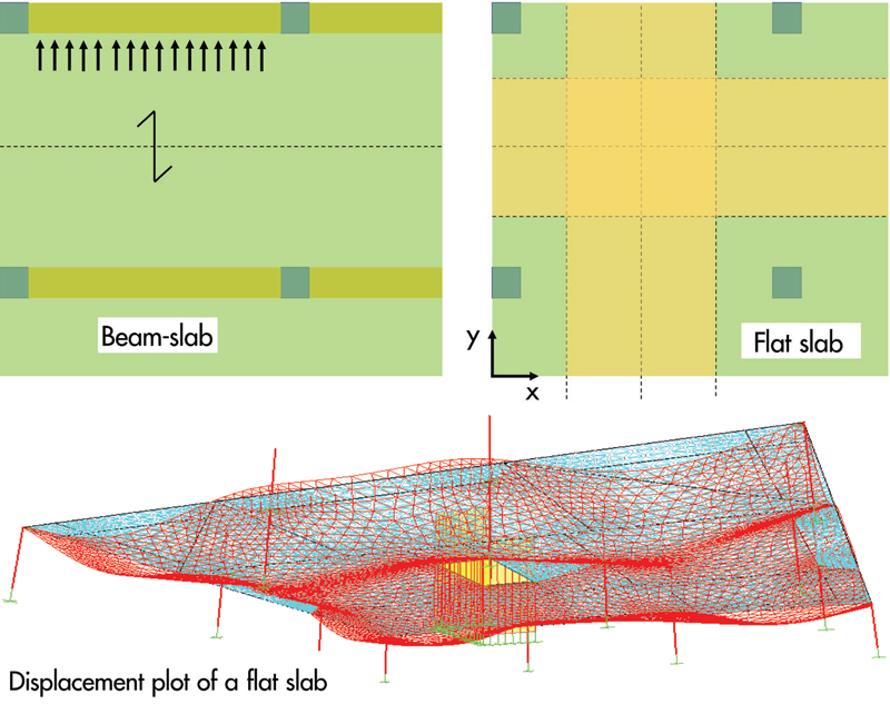
In a different scenario, some builders who are not familiar with beam-slab design may assume that a longer span is always more critical and be tempted to place larger reinforcement in a slab (with full beam supports) in the direction of the longer span, not knowing that the larger moment actually occurs in the shorter span. While builders are not expected to carry out structural design, they should still appreciate basic structural behavior and reinforcement placement concepts.
Works Near Existing Buildings
In many city centers and highly urbanized built-up areas, new development works might inevitably be located close to an existing building. The situation worsens if any excavation for basement or foundation works is required. Some builders make the mistake of excavating right next to an existing boundary wall, not knowing that such excavation work can undermine the foundation of the boundary wall and can cause it to topple (Figure 3). When ground movement is not appropriately controlled (e.g., open-cut excavation), the adjacent building’s foundation may experience movement (lateral and vertical) and cause damage to the super-structure. It is thus necessary to adopt an appropriate earth-retaining system that can limit the ground movements to acceptable levels. It may even be necessary to strengthen the adjacent structures’ ground or foundation in certain circumstances.
Similarly, digging in front of a retaining wall may cause the wall to be weakened, as passive resistance in front of the wall is reduced when soil is excavated. This scenario can occur in hilly areas where retaining walls retain slopes and create usable areas. An overly-zealous contractor could commence excavation in front of a retaining wall without knowing such works could trigger a collapse. It is safer first to understand how construction works would impact the adjacent buildings and structures and then design a safe work procedure with strengthening measures to ensure that the existing retaining wall stability is safeguarded during any digging.
Temporary Support during Construction
There are two main areas to note during reinforced concrete construction: the support of the reinforcement bars and the wet concrete during pouring concrete. Reinforcement bars require some support to hold them in position before concreting. In very thick concrete elements, such as raft foundations or transfer plates, the area of reinforcement bars is likely to be correspondingly large. Some builders might overlook the lateral support required for such heavy top bars and rely on stirrup-type support to hold up these bars. For such cases, it is necessary to design a bespoke support system with adequate lateral bracing to prevent side-sway failure (Figure 6).

Formwork to support wet concrete needs to be snugly fitted and free of gaps that may allow concrete to flow through. This may sometimes be difficult when there are gaps in sloping or uneven ground. When concrete must be cast adjacent to an existing structure, builders must be mindful not to impose additional loads onto the existing structure. For example, such existing structures could be made of a brick wall with little capacity to resist the heavy lateral loads imposed by wet concrete (Figure 6). In addition to designing formwork to take lateral loads, the designer also needs to ensure the overall concrete section or element to be cast does not lean onto the existing structure.
Specifications and Quality Control
Concrete structures can sometimes fail during service life for various reasons, such as deterioration (spalling due to rusted reinforcements), attack by aggressive environments, lack of maintenance, overloading, or unauthorized alterations. Therefore, correct specifications and quality control during construction are critical in ensuring concrete is durable to withstand weathering in its environment. Designers must pay attention to the exposure class and comply with requirements on minimum compressive strength of concrete, cover, cement content, etc. In highly aggressive situations, it may be necessary also to have special additives and protective coatings on reinforcement bars. Supervision and quality control during construction ensures that specifications on paper are met on-site, from concrete production and delivery to handling, placement, and curing.
Building owners should be informed by the designers on the usage of the building and be briefed on allowable loadings on floors, maintenance requirements, and not to make unauthorized alterations. Any unusual sightings of distress (e.g., cracks, deformations, settlement) should be referred to a qualified professional for assessment. Carefully designed reinforced concrete structural elements should have sufficient ductility and should not fail by sudden rupture or instability. Many mishaps can thus be avoided if building owners and occupants pay attention to signs of distress and take early and timely interventions to evaluate and remedy the situation.
Summary
Safe design and construction of reinforced concrete structures require attention to detail. First, the designer can select an appropriate structural system to resist the loads by understanding loadings and load path. Special attention should be paid to silos and flat slabs. Next, it is necessary to appreciate the concept of effective width when evaluating a section capacity under concentric load.
Reinforcement detailing and placement on-site are also important aspects to pay attention to in order to avoid cracking and failure of unreinforced zones of a member. The builder should always remember that wet concrete during placement and heavy reinforcements require robust temporary supports. The various failure modes should be fully understood to avoid underestimating the potential for failure.
Correct specifications and quality control during construction ensure durable structures to prevent premature deterioration. In addition, building owners and occupants have a role in ensuring the continued safety of a building in its service life by performing periodic monitoring and maintenance.■