
The old Social Science Building at Weber State University, located in Ogden, Utah, was constructed in 1970. Programmatically, the building has been one of the most heavily used on campus, serving the social sciences, humanities, and many other departments throughout its life. One would be hard-pressed to find a graduate of the University who had not taken a class there. The concrete building, consisting of one floor below grade and three floors above, remained largely unchanged in its 45-year useful life.
The University’s wish was to completely remove and replace the antiquated mechanical and electrical systems within the building and redesign and reconstruct the architectural space to better serve the ever-evolving student population. Lindquist Hall, as the building would be renamed, is located in Northern Utah, within one-half mile of the Wasatch Fault and in Seismic Design Category D. An initial feasibility study was undertaken to determine an order of magnitude cost-estimate comparison of a complete remodel and seismic upgrade versus demolishing and replacing the entire building. The feasibility study resulted in a decision to keep the building, selectively demolish it down to the structural bones, and rebuild it. The electrical, mechanical, and civil consultants were tasked with designing completely new systems that complied with the 2015 International Building Code while fitting within the confines of the existing structure and the new architectural program, and minimizing impacts to as much of the existing building as possible.
The Structural Engineer of Record (SEOR) was responsible for developing and designing a complete seismic upgrade system for the building. Every floor level consisted of topped pre-cast double tees, and the roof consisted of un-topped single and double tee pre-cast joists. The joists were supported on a combination of cast-in-place and pre-cast girders that were in turn supported on cast-in-place and pre-cast concrete columns or the walls of two separate cast-in-place concrete interior stair towers and a mechanical shaft. These three concrete cores were the lateral force-resisting system for the building.
In addition to the full seismic upgrade, structural repairs, structural modifications, and new structural elements required for the architectural program were designed and detailed. Some of these architectural elements included installing a new elevator shaft within the building footprint, removing two separate areas of floor structure near the building perimeter to create open continuity between multiple floors, and inviting natural light into the core of the building through strategically placed curtain wall systems. The building envelope was also completely replaced with metal stud, and a brick veneer system was placed outboard of the existing slab edge by approximately 16 inches, necessitating the extension of the floor slabs.
Several challenges were identified through an in-depth structural evaluation, and solutions were developed.
- The inherent lateral force resisting consisting of the core walls was insufficient in strength and ductility to brace the building.
Solution: De-couple the existing building from the existing shear wall system and replace it with a modern, ductile, well-performing buckling-restrained braced frame (BRBF) system. This task proved difficult because the concrete cores had to remain intact and support the gravity loads imparted by the concrete girders and joists connected to or bearing on the shaft walls. - The building was extremely heavy, resulting in very large seismic forces.
Solution: Remove the existing, non-performing, un-topped, very heavy pre-cast double-tee concrete roof system and replace it with a light, steel roof framing system with a design-as-required new metal deck diaphragm with necessary chords and collectors. This solution served a double purpose by significantly reducing mass and facilitating the new design of an appropriate roof diaphragm. - Existing pre-cast concrete cladding panels, and their connections to the structure, were determined to have insufficient strength and no ductility to resist out-of-plane seismic and wind forces.
Solution: Remove all the cladding elements from the building and replace them with a combination of new brick veneer backed by cold-formed metal framing and curtain wall systems.
At the time of the initial design and construction, earthquake design was in its infancy, so seismic detailing, including adequate diaphragms with appropriate chords, collectors, and shear transfer elements, shear wall designs with adequate reinforcing and boundary elements, etc., was essentially non-existent. Throughout the building’s life span, a plethora of MEP openings were added to the walls that compromised the integrity of the lateral force resisting system. An extensive pre-design testing protocol identified concrete strengths and reinforcing patterns and was used to calculate existing floor diaphragm capacities. The diaphragm was determined to have adequate shear strength but lacked the required chords and collectors. Furthermore, the diaphragm lacked continuity across girder lines where the topping slab was poured flush with the tops of the girders. Therefore, carbon-fiber overlays were designed and installed to create chords, collectors, and diaphragm continuity across discontinuous planes where required on three floor levels.
The decision to remove the existing roof and replace it with a steel structure was also reviewed programmatically to determine the most economical solution. An independent cost estimate determined that the cost to remove the concrete and replace it with steel would result in a subsequent weight reduction and reduced seismic upgrade requirements. The decision to remove and replace the concrete roof with steel resulted in a cost savings of approximately $1,400,000.
The existing shaft walls are effectively removed from the lateral force-resisting system to allow the new BRBF system to perform as intended. The amplified lateral drift was determined at each level; the intent was to free the upgraded structure from the shaft walls. To accommodate this, while the floor’s shafts actively supported joists and floor girder loads, each girder was cut back to allow up to 3 inches of lateral movement in any horizontal direction at the floors while maintaining gravity support of the in-place floor dead and subsequent required live loads. In addition, the structure was designed to pass over and rest upon the concrete cores at the roof level while allowing up to 5 inches of lateral movement in any direction at the roof level.
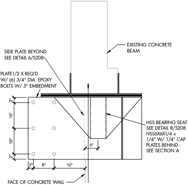
The complex design to support the concrete girders involved a double slide bearing system. Large epoxy-bolted brackets were designed to attach to the core walls with robust bearing seats to support concrete beams that now terminate up to 3 inches from the wall. The double slide bearings consist of Teflon slide bearing brackets positively connected to the beams and slide bearing plates inversely connected to the bearing seats that allow for necessary slide in two directions while maintaining gravity load-carrying ability.
To justify this approach, the existing concrete stair towers and mechanical shaft were analyzed to verify their ability to free-stand within the building, not to impart lateral loads to the structure, or, inversely, to take lateral loads from the structure.

De-coupling the existing building from the existing concrete cores proved to be a complex task. The girders connecting to the shafts and the shafts themselves are all cast-in-place and essentially poured monolithically. The girders are inverted ‘T’ shapes where the pre-cast tees rested upon the the T’s horizontal leg. Because there are many different bearing and connection conditions where the girders support different tributary lengths/areas, the centroid configuration of each girder connection to the shaft was inconsistent in its placement, and the amount of drift accommodation was different at each level of each girder, the reaction does not necessarily coincide with the centroid of the shape. Because of these nonuniformities, each girder bearing end condition is different, and each new steel plate bracket is custom designed specifically for each condition (Figures 1 and 2).

Not only are the girders cut loose and re-supported, but diaphragms are released and detailed to accommodate a similar range of lateral movement. Details were designed and systems installed to ensure the concrete towers were independent. P-delta analyses were also conducted to verify that existing columns would remain stable under the lateral drift of the new system.
Due to the configuration of the existing concrete columns and girders at the building perimeter, all of which were pre-cast and were to remain unchanged, the new braced frame system is designed to fit inside the column/beam envelope (Figure 3). The pre-cast concrete column and girder system is outboard of the original floor plate and serves as exposed elements in the finished building. Because the new frames are intended to sit in-plane with the girder and beam system, the floor plates have been extended up to 16 inches outward to connect, collect, and transfer required forces and tie the BRBF frames to the building for out-of-plane loading. In addition, complex steel systems have been designed to transfer diaphragm collector forces from the new flexible roof, below and out-of-plane, to new braced frame beams that transfer lateral forces to buckling restrained braced frames (Figure 4).

The new braced frame columns are connected at their base to concrete grade beams strategically keyed into the existing concrete foundation walls. The column connections are designed so that once the shear forces within the brace are transferred into the grade beams, they are distributed throughout the entire foundation wall (Figure 5).

Because the existing building is supported entirely on cast-in-place concrete piles, a finite element model was created for the entire foundation wall system. The overturning and shear forces from the braced frames and required gravity loads were applied to verify individual pile strength. Each pile’s vertical and lateral capacity was ascertained by working closely with the project geotechnical engineer and utilizing existing building drawings and original design data. The reduced dead loads from the roof replacement offset the increased seismic loads from the braced frames, and it was determined that new pile loads would be within the capacity of the individual piles.

For its first 45 years, Lindquist Hall at Weber State University, as it is now referred to, stood as one of the most prominent, heavily used, and recognizable buildings on the campus. With the completion of this successful project in 2019, Weber State continues its outstanding legacy of creating modern examples of state-of-the-art, resilient, and sustainable structures on campus for many years to come.■
Project Team
Owner: Weber State University
Structural Engineer: ARW Engineers
Architect: GSBS Architects
Contractor: Big-D Construction
Steel Fabricator: AMFAB Steel Specialties, Inc.