
Cantilevers in many modern buildings exceed historical precedents and proportions. These cantilevers can be unenclosed balconies and enclosed occupiable rectangular volumes of buildings. Enclosed portions of buildings are found in New York City buildings in which the Owners have purchased air rights over adjacent properties or within property lines and above such ground features as driveways. The cantilevers are typically steel-framed for air rights buildings and integrated with diagonals or Vierendeel trusses that extend into the overall building framing. For enclosed occupiable cantilevered stories constructed within property lines, the protruding structural framing is typically steel and attached to the building framing with beam-to-column connections. The last type of framing is of particular interest. The design of long cantilevers, cantilevered enclosed occupiable stories, and atypical back-span conditions require consideration and caution on the part of the designer. Engineers should carefully review layouts, bracing, stiffness, deflection compatibility, detailing, and vibration that can affect more than one cantilevered floor to avoid problems during construction and the long-term performance of cantilevered structures.
Background
At first glance, structural engineers may think of enclosed cantilevered building construction as simple, straightforward structural framing not worthy of an in-depth discussion. They may recall that, in the 1950s, the Brutalist architectural style emerged in Great Britain and spread to other European countries, such as The Netherlands. In 1958, Herman Hertzberger, Tjakko Hazewinkel, and Henk Dicke won the design competition for a University of Amsterdam student housing building, Studentenhuis Weesperstraatm, with a Dutch structuralism design that paralleled Brutalism in the early post-War period. For this building, constructed from 1959 to 1965, the two large enclosed volumes are cantilevered beyond the outermost row of columns. The visual impression of these cantilevered floors is one of substance and structural integrity (Figure 1).

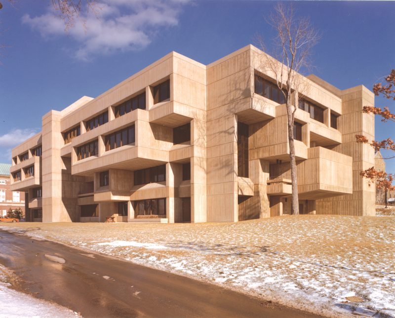
From the early 1960s through the 1970s, several U.S. buildings were also designed in the Brutalist style. The predominant feature of this style continued to be the use of concrete, at least in façades. Another distinguishing feature was large rectangular boxes that protruded (cantilevered) from the main portion of the buildings, typically along one or two bays and over one to two stories in height. Concrete structural members framed the protruding volumes with minimal glazing in the façades. In these boxes, the structural floor depths of the cantilevers and back spans followed long-standing rules of thumb. The ratios of cantilever lengths to back span lengths were no more than 1:3 and sometimes closer to 1:4 (the maximum ratio the author learned as an architecture student). These rectangular protuberances read as rigid sub-assemblages. An example of a U.S. Brutalist-style building is the Folsom Library at Rensselaer Polytechnic Institute in Troy, NY, which was designed by Quinlivan, Pierik & Krause and constructed from 1972 to 1976 (Figure 2). Here, some of the cantilevered volumes appear to be supported from framing just above, but their actual cantilevered lengths are relatively short.
Enclosed Cantilevered Construction Today
By 2000, buildings reminiscent of the Brutalist architectural style started to appear in newly-constructed residential, hotel, and office buildings of about five to twelve or so stories. The protruding rectangular volumes are larger than in the older buildings; they include many more stories and extend along most or all of the bays in the façades. For these buildings, the primary framing is either structural steel or reinforced concrete. The cladding typically comprises a significant amount of glazing or is blank (windowless) stucco or other lightweight walls supported on light gauge steel studs.
The cantilevers may provide clearance for vehicular and/or pedestrian traffic and other activities, reach out over low-rise construction or landscaping at ground level, or take advantage of air rights to extend building cantilevers over shorter, existing buildings. In some cases, the lengths of cantilevered floors increase with increasing elevations. This kind of structural framing configuration may present unique and not often encountered design issues and loadings. The structural designers must also consider long-term performance under gravity loads (i.e., deflection and creep, especially for concrete framing) and torsional response during strong winds and seismic excitation.

In some of these buildings, typically the air rights buildings, the set of cantilevered floors is designed as one multi-story cantilever of multiple bays. However, in others, the cantilevered floors are designed as independent floors, such as enclosed occupiable cantilevered stories. The floors are not structurally tied together vertically through the façade. The bottom cantilevered floor and its back span are the same depth as the upper floors; the lowest cantilever floor does not partially support the gravity loads from the upper floors. Also, the bottom cantilevered floor is not supported by diagonal members from below with clearance for ground activities. A structural plan of cantilevered floors that includes features of this and several other similar buildings is shown in Figure 3a without stairs, an elevator, and holes for vertical HVAC ducts. A cross-section without the foundation, basement parking, bulkhead, and elevator shaft is given in Figure 3b. The cantilevered W12 beams and back-span W12 beams are drawn as “moment connected” to the webs of W10 columns. Still, these connections are semi-rigid, given the flexibility of the W10 columns globally and locally. The beams on Line 2 are subjected to torsion from patterned Live load. The vertical frames on Lines A, B, C, and D provide little lateral load resistance with just one moment connected column. (The adverse effect of the continuous CMU block wall on Line 3 to lateral loads is outside the scope of this article.) Instead, the cantilevered floors are connected to the exterior column with moment connections, many without the stiffening effect of back-span framing on the inboard side of the columns.
On a typical floor, there are two apartments, one between lines A and B.5 and the other between lines B.5 and C. The façades along Lines A and E contain windows. In Floors 2 through 6, bedrooms are between Lines 1 and 2, between A and B, and between Lines C and D. The kitchens are located back-to-back between Lines B and B.5 and between Lines B.3 and C.

Although several loading scenarios may occur, they are not included in building codes. For example, in Figures 4a and 4b, fully loaded 6-foot-tall bookshelves can be placed very close to the tips of the cantilevered steel beams. The bookshelves may be placed in various patterns both in plan and elevation. Their line loads can be significant, perhaps on the order of 72 lbs/ft.

In another example in Figures 5a and 5b, the kitchens are (over)loaded with heavy pots, pans, and equipment. Again, the loading patterns in plan and elevation may differ from kitchen to kitchen. The loads adversely affect the deflections of the cantilevers and result in differential deflections being imposed on the façade material and the glazing in the façades on Lines A and D.

In a third example, an occupant may decide to have a dance party in one of their unit’s bedrooms (Figure 6a). The vibration adversely affects their floors and the others that are “ganged” to it through the light gauge steel framing behind the façade (Figure 6b). Again, the loads adversely affect the deflections of the cantilevers and result in differential deflections being imposed on the façade material and the glazing in the façades on Lines A and D.
Performance
As far as the author has been able to ascertain, no evidence exists of structural stability problems or collapse during the construction of the cantilevered concrete boxes in the older buildings highlighted as precedents. The author notes that, historically, the American Concrete Institute (ACI) and the American Institute of Steel Construction (AISC) focused on the analysis and detailing of structural framing. For example, ACI 318-56, Building Code Requirements for Structural Concrete and Commentary, introduced requirements for the maximum allowable deflections of reinforced concrete cantilevered beams and slabs. Seven years later, ACI 318-63 introduced a replacement requirement for cantilever design, specifically minimum thicknesses for deflection control (if deflections are not calculated) for cantilevered one-way slabs and beams or ribbed one-way slabs. In contrast, the 1936 AISC Specifications focused on end restraint and stresses from moment, shear, and “all other forces.” However, neither ACI nor AISC has provided design guidelines for enclosed cantilevered structural framing or published documents with examples of cantilevered structural framing that possess adequate strength and stiffness for short- and long-term performance. In addition, neither entity has published a collection of failures.
The analysis and design of the structural framing of enclosed, multi-bay, multi-story cantilevered floors present unique challenges for structural engineers, three of them being the lack of redundancy, the complex nature of structural behaviors of members and connections, and the potentially extreme consequences of failure. While rare, failures of these components have occurred during construction, shortly after the buildings have been placed into service, or during longer-term building use.
Extrapolation is conjectured knowledge that entails reaching beyond historically-established knowledge. In any engineering field and even in life, extrapolation inherently elevates risk. Concerning the design of cantilevers, extrapolation occurs when no codified information is available to guide structural engineering design decision-making. This may pertain to structural member and sub-assemblage length and depth dimensions and structural framing configurations.
Some newer buildings have suffered collapses during construction or exhibited structural stability problems, but few have been publicized. Others with potential problems have been discovered before or during construction.
The structural framing of cantilevers exposed to humidity, intense rainstorms, and salty air requires more frequent inspections and maintenance of balconies. The ability to maintain these cantilevered architectural features depends on knowledge and budgets for repair. The knowledge pertains to the original design work (i.e., material selection, structural analysis and design, structural and architectural detailing, and construction quality).
Ongoing Issues
When a structural failure occurs, a forensic investigation is conducted. The objective is to determine technical causes of failure (i.e., lateral-torsional buckling, etc.). Unfortunately, these investigations are often part of a legal matter, and the results are either posted in the public domain or locked away by attorneys. Since the purpose of litigation is to place blame and award monetary sums to injured parties, less attention is paid to how and why these technical failures have occurred than perhaps should have been. In this process, the external and in-house forces on structural engineering designers are overlooked. As a result, opportunities to develop effective feedback loops are missed, and the undue risk of structural failure is neither ameliorated nor reduced.
Architects determine overall building massing and 3-D geometry during conceptual design. Increasingly, fewer structural engineering designers participate in conceptual design and even some or all of schematic design. That is, the role of the structural engineer in building design has been devolving (see Building Design Collaborator or Implementing Technician? by Cohen, STRUCTURE, September 2021).
For newer buildings with cantilevered boxes, historically-established precedents from theory and laboratory testing for design, bracing, and detailing are not being adhered to.
Often overlooked issues include:
- Unsupported ends of cantilevered beams can move or rotate with respect to each other within one floor and among all of the floors vertically, thus imposing varying forces on cladding and its lightweight support framing.
- Not abiding by historically established rules of thumb for maximum ratios of cantilever spans to the back span lengths (1:3 ratio). Longer cantilevers or shorter back-spans may result in stiffness and vibration problems in the cantilevered area. For vibration response prediction of cantilevers from human occupancy and equipment, see AISC’s 2016 Design Guide 11: Vibrations of Steel-Framed Structural Systems Due to Human Activity (Second Edition) which recommends finite element analysis.
- Not providing back-spans for cantilevered beams. Cantilevered steel beams are framed into structural steel columns, often into column webs. In this configuration, the rotational restraint, stiffness, and local deformations must be accounted for in a design. These cantilevered beams may also be framed into girders acting in torsion. The torsional strength of the beam and rotational stiffness also affect the cantilever strength and deflection. In some cases, the architectural design does not lend itself to column locations that would allow back spans for the cantilevered beams. Cantilevered reinforced concrete slabs occur without being framed into perimeter spandrel beams; these slabs are cantilevered from interior slabs that often have no perimeter or interior beams.
- Bracing the compression (bottom) flanges of steel beams leads to structural instability. To determine if bracing is needed, the 4th Edition of the Guide to Stability Design Criteria for Metal Structures published in 1976 provides guidance founded on previous work dating back to 1960.
- The constructability of complicated connections. Often, the difference between member sizes is insufficient to implement clean, simple, structurally efficient details. For example, flange-bolted beam-to-girder moment connections require bending bottom plates and possibly using shims. In another example, for beam-to-HSS-columns, the beam flanges can only be partially welded to columns because they are wider than the (flat portion of the) columns.
- Determining the deflections at the ends of cantilevers is much more complicated than the simple calculation with a uniformly distributed load on the cantilever. Various load combinations need to be taken into account: 1) dead, 2) dead + uniform live, 3) dead + patterned live load, 4) dead + live load that includes concentrated loads at/near the tips of the cantilevers, 5) dead + dynamic vertical loads from human activity, 6) dead + code-specified live + vertical response of cantilevers from seismic excitation, and so on.
- Camber, likely more than “natural camber placed upward during erection,” must be specified on structural drawings. Differences in fabricated camber for cantilevered steel beams and cantilevered reinforced concrete slabs will affect the exterior wall framing. Spandrel beams, especially those supporting facia materials, do not lend themselves to cambering.
- The detailing of the trim beams behind the façade (perhaps W10s) that frame into the cantilevered members may require on-site modifications because the cantilevered members are not necessarily horizontal or at the same elevation at their tips.
- Cladding, such as all glazing, requires specialized cladding-to-frame connections (often proprietary) to accommodate the static, vibrational, and time-dependent random cyclic movement of the cantilevered construction.
- Cladding is directly exposed to outside temperatures. Its thermal movements from extreme cold and extreme heat need to be accommodated without imposing any stresses on its support framing or the cantilevered floors.
- Over time, there is a chance that cantilevered steel or reinforced concrete members may exhibit short- and long-term deflections due to overloading the cantilevered framing, patterned live loads not initially taken into account, shrinkage of various materials, creep (of concrete), and thermal effects. Excessive deflection introduces potential performance problems of brittle cladding material such as stucco and glazing, detrimental deformations in joints, sealants, and window gaskets, and buckling of mullions.
The structural design and detailing of enclosed cantilevered stories are not as simple as the trivial task of calculating moments, shears, and deflections. However, relevant knowledge is available to modify the architectural design to reduce risk. Hopefully, this article will serve as the initial framework to establish a feedback loop into structural engineering practice.
Acknowledgments
This article was sponsored, in part, by Grant No. 1724829 from the Science, Technology, and Society program of the National Science Foundation and by a donation from an anonymous senior U.S. structural engineering practitioner.■