
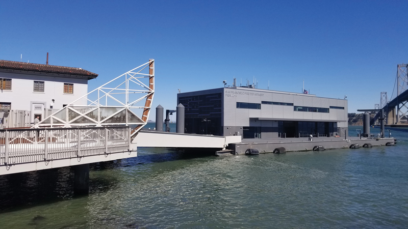
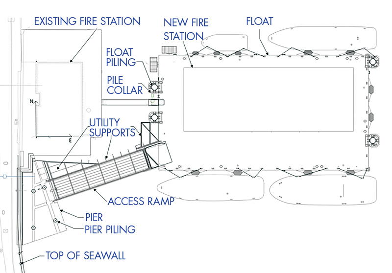
San Francisco’s new Fireboat Station No. 35 is a floating two-story, 16,000-square-foot building at Pier 22 ½ supported by a 173-foot-long by 96-foot-wide by 9-foot-deep steel float moored by four guide piles behind San Francisco’s historic Fire Station 35 building. The station includes a new steel pier and associated steel support piles adjacent to the Embarcadero and historic timber pier, a vehicular and pedestrian ramp between the steel pier and float that supports the building, and a gangway between the float and historic timber pier for the firefighters (Figures 1 and 2).
A Unique Project
When first conceived, the project’s primary objective was to develop a one-of-a-kind floating fire station facility meeting modern standards and resilient to sea-level rise. As an essential facility, Fireboat Station No. 35 is designed to remain operational after the 100-year design storm and the Design Earthquake as defined by the American Society of Civil Engineers Standard 7-10, Minimum Design Loads and Associated Criteria for Buildings and Other Structures. Having an essential facility on the water will allow the San Francisco Fire Department (SFFD) to immediately deploy marine units to locations in the Bay Area that might experience extensive damage from seismic or fire events and are not accessible by roads. The facility also serves as SFFD’s marine-based Emergency Operations Center and includes a large multi-purpose Boson/Ambulance room, shops, and boat/dive gear storage. The new building design is considerate of the existing station and other buildings within the Embarcadero National Historic District.
A Collaborative Effort
The success of this project is due to the collaborative efforts of the owner, San Francisco Public Works (SFPW), and the Design-Build team. The project schedule required the building and marine design to be performed simultaneously, rather than the more typical progression of completing the building design before the float design. This required close coordination between the building and marine designers to ensure the various structures were compatible and met the project criteria.
Fabrication also required close collaboration between many parties. The steel float, pier, access ramp, and pilings were fabricated in China and transported on a barge to Treasure Island in San Francisco. While the building was constructed on the float, the piles and pier were installed at Pier 22 ½ in San Francisco. After the building was constructed, the float with the building was towed to Pier 22 ½, where it was connected to the piles, and the access ramp was installed.
Design and Structural Systems
The design team’s initial work included workshops with SFFD to discuss project programming, operational needs, and safety requirements for the new facility. With that knowledge, they developed a program narrative and basis of design consisting of design criteria such as float motions for occupant comfort, seismic performance criteria, design standards, and applicable codes and requirements.
A float moored with “guide” piling is a common structural system on the water to accommodate changing water levels due to waves, tides, and sea-level rise, and to facilitate access to berthed vessels. The float is a rectangular steel box with watertight longitudinal and transverse bulkheads and transverse trusses. The box shape is frequently used for stationary floating structures in the water. The length, width, and depth were based on multiple factors, e.g., fire department operations such as fireboat berthing and ambulance access, building size and access, stability, pile loads, and cost. Multiple float compartments were ballasted with fixed or water ballast to level the float and meet the required operation freeboard.
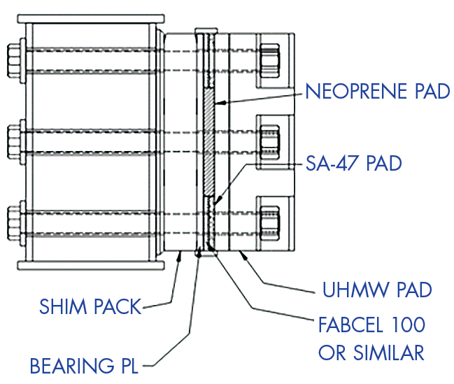
Compared to other projects with float-piling systems, one unusual aspect of the project was the float motions needed to typically meet allowable “Cruise liner” accelerations and rolls to accommodate the firefighters living in the facility during their shifts, including eating and sleeping. It was challenging to meet these limits while providing the required pile strength to resist the wave, wind, and berthing loads. To meet both requirements, a dampener system was introduced between the pile collar and ultra-high molecular weight polyethylene (UHMW) bearing pad to provide significant cushioning, reducing the float-pile impact by up to 90 percent. The system is composed of various reinforced and unreinforced rubber pads between steel plates (Figure 3).
The float and building elements were coordinated during design to facilitate the construction. The bulkheads are located to support many of the building walls. The building columns extend through the float, typically adjacent to a bulkhead, with a stub extending above deck for the building column connection. Steel curbs were welded to the float deck to support the building walls.
The building design accommodates the stresses created by thermal deformations of the steel float from daily solar differential heating and seasonal water temperature changes. In addition, the design accounts for axial forces and moments due to daily, seasonal, and storm waves, as well as wind and seismic loads.
The building’s gravity system is composed of a 3-inch metal corrugated deck with 6 inches maximum of lightweight concrete fill, supported on wide flange composite beams and girders connected to hollow structural steel (HSS) columns.
The building’s lateral system is composed of buckling restrained braced steel frames in both the longitudinal and transverse directions to prevent excessive lateral deflection of the structure. The columns and braces are connected to one another by gusset plates.
A simple seismic base shear comparison between a floating structure and a land-based structure indicates a notable reduction in base shear for the floating structure; this behavior is related to the water damping and being supported by the long period float-piling structure. A time history analysis of the float-piling system confirmed the design storm motions controlled over the earthquake motions. The 100 Year Storm dynamic accelerations for the building were combined with the response modification factor, R = 8, to account for yielding, as allowed by the code.
Special load combinations were implemented to include all the possible load case scenarios with load case factors coordinated with the marine structural engineers; wind load combinations mainly govern the building’s structural design.
The entire structure was designed to maintain a stress ratio of less than 0.3, which represents the fatigue threshold specified by the steel code. This criterion will help ensure the continued safe performance of all the connections through the full design life of the structure.
Seismic Systems and Sea-Level Rise Protection
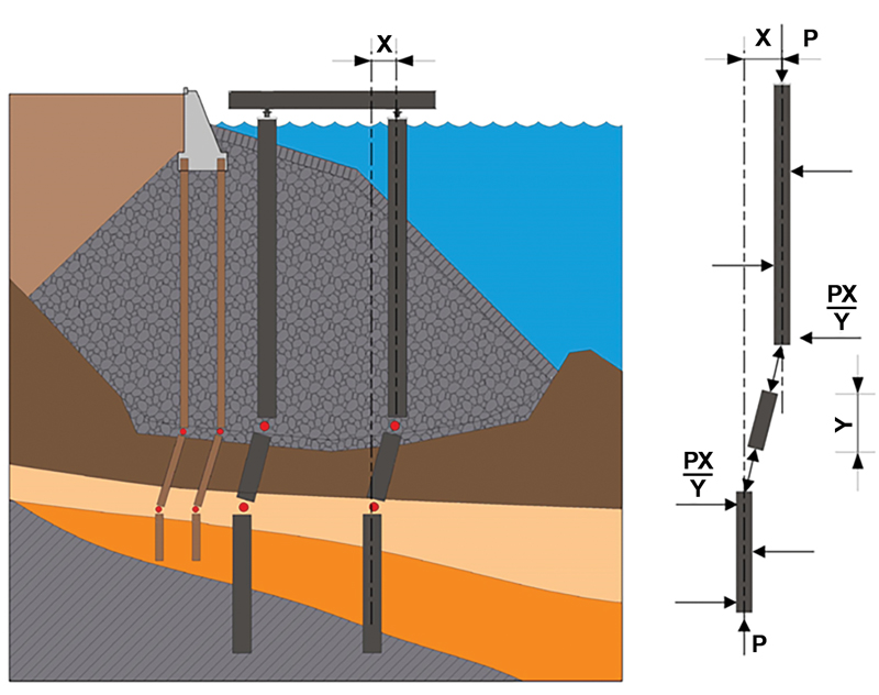
One of the most challenging marine engineering items was designing the steel pier piles for earthquake movements of the existing seawall. The piles are installed through about 50 feet of seawall rock embankment (Figure 4). No seawall design or strengthening was performed for this project. Instead, the pier piles were designed to deform plastically without buckling from the embankment lateral earthquake movement and still resist the earthquake inertial loads and design vertical loads, and remain functional.
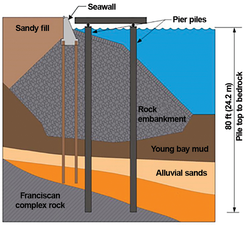
An extensive analysis estimated that the rock embankment would move about 11 inches toward the Bay in the controlling Contingency Level Earthquake due to the relatively weak soil layer beneath it. To better understand the soil layer’s strength, sonic drilling methods were used to complete borings through the rock embankment. The analysis also indicated that the rock embankment was strong enough to remain mostly intact so that two plastic hinges would form in the pile, one below and one in the embankment. Figure 5 shows the hinge locations and free body diagram.
The facility is designed to accommodate the seawall, pier, and access ramp movements and to remain operational after the controlling Contingency Level Earthquake. Some repairs may be required landside of the seawall due to the waterside movement of the seawall and the settlement of the sandy fill. Still, the gap and settlement can be accommodated with temporary bridging plates across the gap to provide access to the facility.
Due to storms and earthquakes, the structures need to accommodate significant relative displacements and rotations. These are accommodated in many ways: a seismic gap at the pier-to-land interface, a kingpin and vertical support Teflon sliding bearings at the pier-to-access-ramp interface, wheels at the access-ramp-to-float interface, and transition or bridging plates at all interfaces. In addition, the access ramp supports undergo continual movement, so they are designed with low-friction, self-lubricating marine bearings.
The utilities running from the land to the building on the float must also accommodate relative movements of up to several feet. As a result, flexible conduits were used at multiple locations, and additional structure was required to support and protect the conduits.
The pier is designed to integrate with the existing San Francisco Embarcadero, so the deck elevation matches the existing sidewalk and historic Fire Station 35 timber pier deck. However, those elevations are below the projected Total Water Level for the 50-year project design life. So if the deck elevation needs to be raised for future sea-level rise, the pier superstructure can be removed as it was installed (i.e., by lifting with a floating crane), pile extensions added to the existing piles, and the pier superstructure reinstalled onto the extended piling.
A Facility for the Future
The successful collaboration of the numerous stakeholders on this complex project resulted in a facility that will protect the San Francisco Bay Area well into the future.
The project adds to the structural engineering body of knowledge in several areas. The project work determined the following:
- Earthquake loads on floating structures can be significant and should be considered.
- Multiple plastic hinges in pier piling may be acceptable, depending on the ability of the soil to stabilize the pile.
- A practical method to dampen the movement of a float on piles by using a dampener system between the pile and pile collar.■
Reference
Faltinsen, O.M. (1999). Sea Loads on Ships and Offshore Structures. Oxford University Press