
Park Designed by Diller Scofidio + Renfro (design architect) and Arup (engineer of record), the Park Union Bridge opened to pedestrians in July 2021, connecting the U.S. Olympic and Paralympic Museum to America the Beautiful Park and Downtown Colorado Springs. The bridge is called the rip curl for its cresting design; the footbridge spans 250 feet over active rail lines (Figure 1).
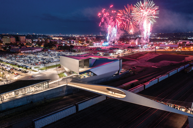
One of the key project successes for the design team was producing a design that balanced achieving the aesthetic vision and minimizing the impact on the railroads below.
From bridge inception, the designers leveraged their parametric 3-D work environment to communicate visually and explain crucial aspects of the bridge behavior among themselves and with key collaborators of the project team.
Structural Analysis
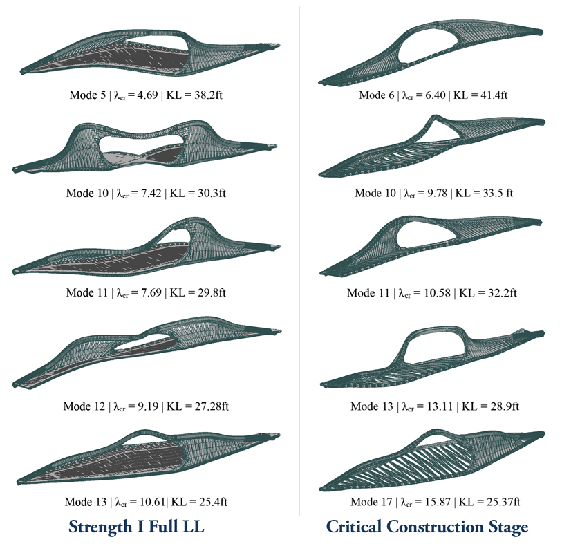
Long-span footbridges are challenging by nature due to their high span-to-width ratios; dynamics become a significant consideration. Additionally, the form of the Park Union Bridge, composed of a structural steel shell simply supported on concrete abutments, is one of the most unique bridge typologies. To realize this structure, the design team conducted global, modal, spectral, footfall, buckling analysis, and wind tunnel testing. Figure 2 demonstrates an output from the robust analysis used to validate the concept; the buckling arch analysis confirmed that the slender area of the steelwork in compression would remain stable under all applicable load cases and load combinations following AASHTO LRFD Bridge Design Specifications.
The design team collaboratively massed, rationalized, and managed the steelwork 3-D model in Rhino with a Grasshopper parametric plug-in. All analysis was completed in Oasys GSA, which linked parametrically to the 3-D steelwork model. This allowed for fast updates to structural analysis models as the design iterated and facilitated rationalizing the steelwork. While the rip curl geometry is captivating in its unusual form, the shape is predominantly built from flat and single curvature plates, which was key to simplifying fabrication.
Rowan Williams Davies & Irwin Inc. (RWDI), located in Ontario, Canada, was commissioned to design and build an aeroelastic model to evaluate the bridge’s wind-induced responses.
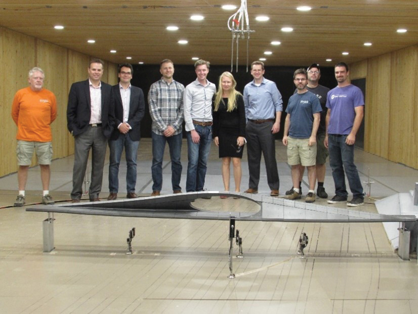
The aeroelastic model was tested in a fully turbulent boundary layer wind tunnel that accurately simulated the approaching wind conditions. Arup observed the test to determine that the bridge was aerodynamically stable (Figure 3).
The view inside the bridge (Figure 4) demonstrates the close relationship between architecture and bridge engineering: pedestrian headroom clearances and the desire to minimize the depth of the bridge elevation aesthetically were closely coordinated with arch span-to-depth ratios and arch cross-section shaping.
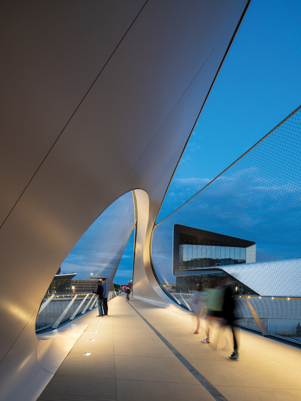
Another barely visible element in Figure 4 is the protective parapet; a significant design success lies in its translucency. Railroad parapets on bridges have strict performance criteria and are notoriously known to impact bridges’ aesthetics negatively. The Arup Facades team produced a performance specification for a tension net structure that met the performance requirements for Union Pacific Railroad without impacting the aesthetic vision for the crossing; this included a maximum opening size of one and a half inches and the ability to resist a climber. The stainless-steel mesh is held by a cable spanning from steel shell to parapet post; the sag of the cable is specified such that a minimum ten-foot height requirement for railroad parapets is always maintained.
Structural Details
Building over railroads presents unique constraints both in design and construction. Maintaining railroad operation unimpeded during erection was a crucial driver in the design; the yard includes thirteen rail tracks including two through tracks with freight train traffic of approximately ten trains per day.
The superstructure comprises the steel shell, floor beams, and concrete deck on stay-in-place (SIP) metal deck form. The pinnacle of the design effort was the designers collaborating on shaping the 300-ton steel superstructure. The steel shell is further rationalized into three elements: the edge girder, the asymmetrical arch, and the stiffened steel web (steel shell) linking the two.
Shallow box construction was critical for achieving the architectural vision while providing a robust structural solution. The edge girder and arch sections are built up similar to a lidded box: three pieces of the box are built up assuming access from the inside is available, and the final capping plate is welded on from the outside only as the box is too small to access from inside. Fillet welds are used where possible to minimize welding requirements.
The derivation of the asymmetrical arch box required close collaboration with the architect. The arch carries approximately 5000 kips in compression. The arch deviates from the natural parabolic shape to meet architectural aspirations; therefore, a gravity bending moment is induced into the section. The asymmetry in plan causes an additional lateral bending moment. The size of the arch box directly influences head heights and internal cladding requirements. 70 ksi steel was used in the arch section to minimize the overall size and plate thickness of the highest loaded member on the bridge. Higher-strength steel allowed plate thicknesses to remain below 2 inches, making welding and building up the section more cost-effective.
The structural solution facilitated erection over the railway, assuming all components would be assembled in a staging area before erecting the nearly finished bridge in a single railroad outage. The steelwork was fabricated and painted off-site at King Fabrication in Houston, TX. This ensured the quality of production and limited the impact of construction on-site. In addition, the fabricator fully fit up the bridge before the shipment of pieces to validate the fabrication geometry and camber. Finally, the design team strategically located bolted splices in floor beams and permitted welded field splices in the arch and edge girders to facilitate transport to the site and assembly. The pieces were delivered on multiple trucks from Houston to Colorado Springs.
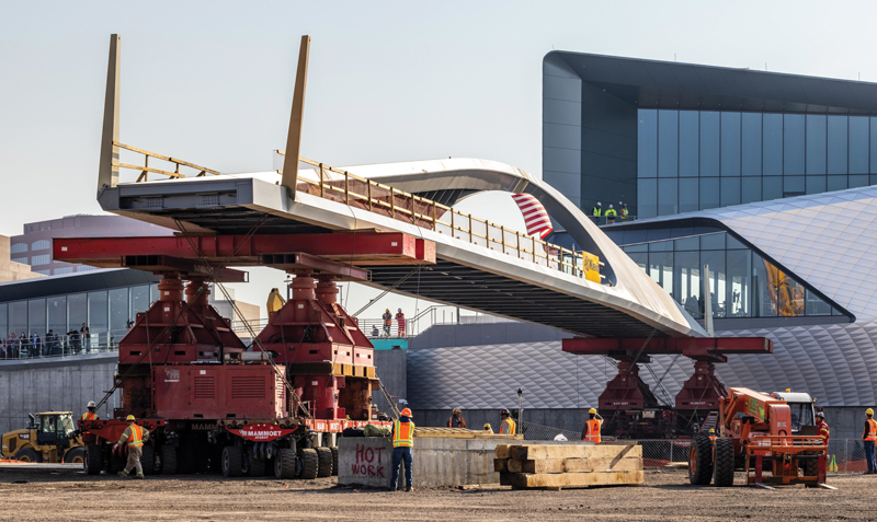
Kiewit started the construction of the bridge in early 2019. The concrete deck was cast once the superstructure was assembled in a staging area adjacent to the rail yard. In October 2020, the 550-ton superstructure was lifted by self-propelled modular transporters (SPMTs) and driven (by Mammoet) into its final position in under five hours, ahead of the allowed railroad outage window (Figure 5). Railroad track protection was provided for the drive to ensure SPMT wheel loads did not damage the railroad infrastructure. The bridge was then fit-out from the inside, minimizing additional railroad closures.
Conclusion
The gravity-defying bridge enhances the landscape of Colorado Springs. The collaborative communication style was continually enhanced by cutting-edge design tools and allowed the preservation of the bridge’s sculptural floating nature while balancing the aesthetic with a pragmatic and sensible design over the railroad. The Park Union bridge is a recipient of the American Public Works Association Colorado Award and two Structural Association of New York “Excellence in Structural Engineering” awards (first place in Other Structures and Engineer’s Choice Award).■
Project Team
Owner: City of Colorado Springs
Structural Engineer of Record – Superstructure: Arup
Structural Engineer of Record – Abutments: KL+A (as a subconsultant to Arup)
Design Architect: Diller Scofidio + Renfro
Lighting Designer: Tillotson Design Associates
Architect of Record: Anderson Mason Dale (executive architect)
General Contractor: Kiewit
SPMT Erector: Mammoet
Steel Fabricator: King Fabrication