
Overview of Structural Behavior, Challenges, and Opportunities
Reciprocal frames (RF) are a family of structures that increasingly are attracting interest from many participants in the construction industry. They offer architectural opportunities through their expressive form and structural advantages due to their specific configuration. This article describes what makes this type of structure so different from other systems.
A possible definition of a reciprocal frame is a grid of linear members where each member simultaneously supports and is supported by its neighboring members. Therefore, the members are structurally interdependent and in a structural hierarchy of equal importance. Although the basic RF configurations are typically used to enclose a regular rectangular/polygonal plan form, current built cases have also presented reciprocal frames with irregular shapes. Up-to-date digital design tools enable a broad spectrum of opportunities for RFs, facilitating the design and fabrication of complex RF geometries and building typologies for diverse purposes.
Reciprocal frames have been known for centuries, and there are numerous examples from the Middle Ages, Renaissance, and later periods from studies/drawings and built examples. Traditionally these frames were made of wood, the most readily available linear building material. They were used in buildings and bridges for permanent and temporary structures. Reciprocal frames are also known under the term nexorades in some literature. The British inventor Graham Brown built a number of reciprocal frames and coined the term reciprocal frames in the 1980s. However, it was only much later that the structures were researched and analyzed in depth.
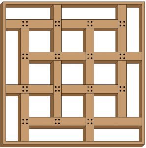
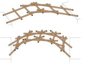
Historically they were used in flat beam systems for forming floors in covered spaces where the span exceeded the available timber lengths, spanning over circular or rectangular spaces, as illustrated by Sebastiano Serlio (Figure 1). Leonardo da Vinci sketched reciprocal frames as temporary bridges using a system of timber beams to create a simple structure with relatively short timber members and simple connections, which would have been easy to construct (Figure 2). The timber members are used as they are, without any cuttings/notches, and are simply held together through friction.
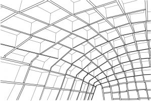
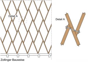
The RF has also been used for curved structures such as vaults or domes. The Zollinger frame, developed by the German engineer Friedrich Zollinger and patented in 1926, is also a type of RF structure. The Zollinger frame can form a vault by using short lengths of timber that are connected at the half-points with equal elements forming rhombic (diamond) shapes. The connection of RF beams occurs at the same level, unlike a typical RF structure where the beams are sitting on top of each other after transferring the loads through notched carpentry connections. As a result, the load path in the Zollinger frame is more direct than in ordinary RFs because the members are at the same level due to the connections. Therefore, compression is dominant. Figure 3 is a drawing of a built Zollinger Frame, Alvaro Siza’s pavilion for the Serpentine Gallery in London constructed in 2005. The structure uses a common type of connection detail where all members are connected in the same plane, thus avoiding eccentricity and ensuring an efficient load transfer. However, the members are connected with a small offset in the plane, simplifying the execution of the connection (Figure 4).
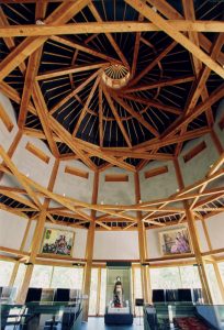
In recent years RF structures have been used relatively frequently in Japan, building on a long tradition that has utilized timber and traditional connections. A prominent example is the Seiwa Puppet Theatre, Kumamoto, Japan, by architect Kazuhiro Ishii (Figure 5). The puppet theatre forms part of a cultural center with several buildings consisting of various reciprocal frame types.
What Makes Reciprocal Frames Special?
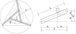
The simplest reciprocal frame consists of at least three linear members connected in a circular way to form a flat or pitched structure spanning a triangular or round plan space (Figure 6). The simple three-member structure can be expanded with more beams to form a roof over rectangular or polygonal spaces. When the members are connected, a multifaceted area is formed. For the simple three-member frame, this is a triangular area; for a six-member frame, the space forms a hexagon.
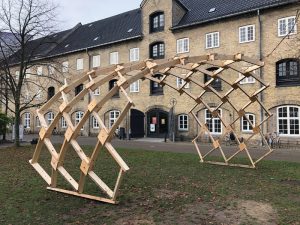
The simple frames described above can be connected to create complex structures, such as domes, vaults, or free-form structures. For example, a small team erected a complex reciprocal frame structure in Copenhagen in 2017 using only handcraft and no machinery
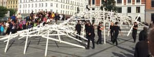
(Figure 7). The structure was erected in just 15 minutes. Note that the relatively low friction between the timber members and the paved street surface is sufficient to stabilize the structure.
Materials
In principle, all materials such as concrete, timber, or steel can be used in RFs. However, in practice, timber is best suited to the structural type because of its natural linear form. Thus, unsurprisingly, the majority of RF-built examples are in timber. In addition, especially at present, RF research focuses on timber because it is versatile and sustainable. Current RF research explores the possibilities of using short-length, re-used timbers to construct reciprocal frames, which further reduces the already low carbon footprints of RF structures.
An unusual example of an RF structure where steel instead of timber was the primary construction material is the Rokko-Shidare observatory near Kobe, Japan (https://bit.ly/3vTcvUs). The observatory is positioned at the top of a mountain, and the structure consists of tubular steel members with connections using thin and flexible steel ties.
Structural Behavior
RFs are a family of beam grid structures. Fundamentally, the reciprocal frame members are supported at each end and carry the load from one or more neighboring members along the length. Compared with better-known types of structures such as grid shells, grid domes, or trusses, forces in these structures are mainly transferred via normal forces, compression and tension, and forces are transferred at the ends of members. The forces in reciprocal frames are transferred mainly via bending and shear in the members and are transferred both at intermediate points and endpoints of members.
If a load is applied to the structure at any point, all the other members contribute to transferring the load to the supports. This is a unique aspect of reciprocal frames: all the members have structurally equal importance (i.e., there is no hierarchy of primary and secondary elements as in most other structural frame systems). All elements in an RF rely equally on the neighboring elements for support and provide support to the same elements in return. In this type of structure, robustness and progressive collapse are essential issues to be dealt with. In very simple reciprocal frames arranged in a closed circuit (for example, forming a structure with one RF closed polygon with 3, 4, or more beams), removing one member would typically lead to a collapse because all members are structurally interdependent. However, this problem can be overcome by using multiple, interconnected frame systems with inherent redundancy because they have multiple alternative load paths. There is also the possibility of designing the joints with a degree of rigidity (i.e., bending capacity), which adds redundancy and, therefore, robustness to the structure.
In RFs, bending is dominant, especially in the region of the beams where they support neighboring members. The relationship between the engagement lengths (distance between inner supports in relation to outer beam supports; lengths x1 and x2 in Figure 6) determines the relative size of shear force and bending. In frames with a curved shape, there are also normal forces in the members; the greater the curvature, the greater the normal forces in relation to the dominant bending and shear. However, the size of the normal forces also depends on other factors, such as the eccentricity of the connections.
The eccentricity (e) is defined as the vertical (orthogonal) distance between centerlines between two connecting members (Figure 6). RFs start to behave like regular beam grid structures when e is made smaller. Load paths in RFs cannot always be intuitively understood. The beam depth and the eccentricity at the connections are essential parameters in the form-finding, and structural design cannot be separated from detailing.
Form-finding in three dimensions requires advanced computational tools for larger and more complex RF structures. The complexity of RF design is successfully handled through current parametric design tools, offering possibilities of optimization and reduced material use. For example, Rhinoceros 3D and Grasshopper are parametric design tools used to define overall geometry and superimpose an RF pattern over the main geometry. The analysis tool Caramba is an example of an analysis tool that has been used for RF frame systems.
Effects of creep in timber are important and need to be considered in the analysis. Deformations in RF structures are generally larger than in similar span regular structures. This is mainly due to the relatively large number of connections, which in timber are less rigid than in other materials.
Challenges
One of the main challenges of designing large, complex RF structures is defining geometry. In addition, the interdependence of the structural parameters increases the challenge. Advanced form-finding tools are therefore required. The experience hitherto has been that parametric design tools offer the best possibilities in defining, fine-tuning, and optimizing the overall geometry.
The following stages follow a typical design process:
- Define the overall geometry, including beam sizes.
- Apply a mesh to the overall geometry.
- Define an RF pattern with the help of the mesh. (An iterative process can follow where the overall geometry and the RF frame are changed).
- Develop the structural model.
- Model and design the connections.
Detailing
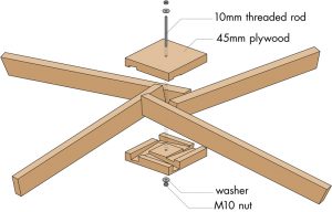
Connections in RF structures are formed by joining only two members at one point, making the connection assembly straightforward. When using timber, to reduce the number of connections, joints can be simple contact bearings (one on top of the other) or use a cutout (notching) or a build-up (addition). Members can also be positioned in the same plane, for example, the clamp connection in Figure 8. The clamp connection was used in an experimental structure erected temporarily at the School of Architecture in Copenhagen. All the timber used in the RF members and for forming the connections was second-hand reclaimed timber (Figure 9).
Notches in timber members are often difficult to avoid depending on the connection type. A general aim is to reduce the eccentricity, as previously mentioned. In addition, notches reduce the section capacity, which needs to be considered in the design, as shear forces are often dominant and can be critical.
In timber, direct contact pressure, which can transfer shear force via compression perpendicular to the grain, is most efficient. This requires a good contact area with precise notches, which can be accomplished using advanced 3-D cutting tools (Figure 8).
Small torsional moments occur due to the geometry of the connections. The analysis can eliminate these by setting the torsional bending capacity to near zero in the FEM software. Actual torsional moments are typically much smaller than the torsional moment capacity.
The structure often requires simple temporary supports during erection that can be moved up as the construction progresses.
An Example
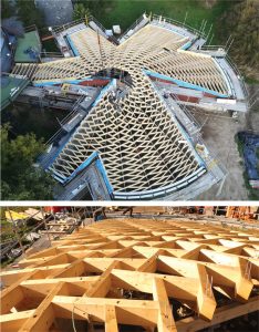
A recently constructed reciprocal frame with complex geometry is the Franz Masereel Centre in Kasterlee, Belgium. The project is a collaboration between LIST Architects, Bureau Bouwtechniek, and Bollinger+Grohmann Engineers and consists of an extension to the existing Franz Masereel Centre. The structure is comprised of a truncated cone forming the walls and a timber structure of interconnected 4-member reciprocal frames. The overall complex geometry has a number of cutouts, showing the full potential of RFs in creating roof enclosures through up-to-date computational design and fabrication tools (refer to the aerial view of the building and roof detail in Figure 10).
The Future of RFs
Reciprocal frames (RF) are structures with novel geometries and form language, attracting increasing interest among architects, engineers, and clients. The advantages are, among others, that they offer opportunities to use relatively short members and that timber is often the most suitable building material, thereby lending itself favorably to the sustainability agenda. However, multiple RFs are typically geometrically complex, and the load paths cannot be intuitively determined. Therefore, it requires parametric design tools to reach an optimal form and to make it possible to analyze the structures.
Hopefully, in the future, further research and built examples will increase the theoretical and practical knowledge of designing and constructing these still relatively unknown types of structures.■
References
Olga Popovic Larsen: Reciprocal Frame Architecture, Elsevier Architectural Press (2008).
C. M. Castriotto, O.P. Larsen, X. Browne, et al., Clamp links: a novel type of reciprocal frame connection.
O. Bavarel: Nexorades, a family of interwoven space structures. (2000).
Udo Thönnissen: Hebelstabwerke/Reciprocal Frameworks, tradition and innovation, GTA Verlag.
Bergis and De Rycke: Reciprocal Frame for the roof of the Franz Masereel Centre. Proceedings of the IASS Annual Symposium 2017.
Baverel and Pugmale: Reciprocal systems based on planar elements (2013).
X. Browne, O.P.Larsen, C.M.Castriotti: Utilising waste wood through reciprocal frame systems.