
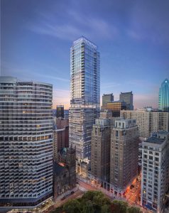
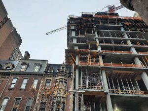
The Laurel Rittenhouse Square is a 50-story, 583,000-square-foot residential tower currently under construction in Philadelphia. Located on the last undeveloped parcel on Philadelphia’s prestigious Rittenhouse Square, the project features an ultra-luxury mixed-use tower consisting of 65 condominiums and 184 apartments on top of a three-story podium with 44,000 square feet of retail and dining spaces. Once complete, The Laurel will rise 604 feet, making it the tallest residential building in Center City.
The 50-story tower is constructed of a cast-in-place concrete flat plate system with concrete shear walls. A portion of the podium outside the tower’s footprint is a steel-framed structure. Two concrete below-grade levels accommodate mechanical equipment space and parking.
Foundations
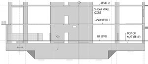
With cost estimating assistance from the Construction Manager, Hunter Roberts, a concrete mat foundation was chosen as the most cost-effective solution. The mat thickness varies from 15 feet under the building core to 7 feet outside of the core and extends throughout the footprint of the main tower. This allows the engagement of all tower columns and the requisite dead loads to resist the overturning forces on the foundation. It further spreads the tower loads out over the entire footprint. Studies determined that differential settlement was approximately ½ inch and total building settlement was 1½ inches, which was deemed to be within serviceable limits for the project.
A 6,000 psi concrete was chosen, using a 70% slag cementitious substitute mix to slow the heat of hydration and, therefore, heat gain in the concrete. In addition, a compacted stone-filled space, 2.5 feet thick, was left between the basement floor and the top of the mat foundation to accommodate installation and future access to utilities under the slab on grade floor slab at the lowest basement level.
Tight Urban Site
Because existing buildings and public streets surround the site, and the project occupies nearly all the site, construction methodologies needed to be considered in the structural design from street level down.
The entire structure below grade was concrete construction. To allow for the tower’s construction, the grade level floor outside the tower footprint was designed for construction material storage and construction equipment loads, including a mobile crane.
Foundation walls were designed to be constructed using a one-sided form system. The exterior side of the wall would be placed against the blind side waterproofing applied to the support of the excavation (SOE) structure. This required accommodation of more liberal tolerances consistent with SOE systems, including accommodating variations in the thickness of the wall and coordinating the interior spaces to accommodate that variation. The foundation wall’s inside face was located such that any variation in the SOE system would be accommodated on the outside face of the foundation wall while maintaining minimum wall design thickness.
The mat foundation was placed directly against the SOE on all four sides. This also required that reinforcing steel accommodate the potential variations in SOE location.
Once the excavation was complete, the mat foundation construction began. The most practical solution was to place the entire mat in one continuous pour. This required the placement of 400 tons of reinforcing steel, the design and installation of a “standee” system to support the top reinforcing steel mat (that remains in the concrete permanently), and the placement of 4,360 cubic yards of concrete using 440 concrete trucks.
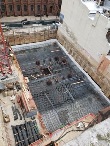
To access the project site with this many concrete trucks required concrete placement through the night and on the weekend to accommodate street closures. Due to the mass concrete placement having the potential to generate heat and differential temperatures within the mat, special considerations were implemented in the design and testing of the concrete mix. In addition, insulated curing blankets were placed on top of the mat to reduce temperature loss at the top surface and avoid potentially damaging temperature differential through the concrete. Sensors were placed throughout the mat and were connected to a central monitoring computer to confirm that the temperatures throughout the depth of the mat during curing were below recommended limits per the American Concrete Institute’s ACI 207.1R, Guide to Mass Concrete.
The concrete placement began at 1:30 AM on a Saturday and was completed in 12 hours. The process resulted in temperatures within tolerance per ACI 207.1R, and all concrete was placed without delayed wait times in trucks.
Tower Occupant Comfort and the Lateral System
Studies were undertaken to assess the best system to address wind-induced motion in this tall tower. RWDI performed preliminary wind analysis and the final wind tunnel testing. The results were used to develop structural loads and to assess wind-induced motion for occupant comfort. An iterative process was applied to optimize the structure, balancing wind-induced accelerations against structural size and cost.
The use of a supplemental damping system to reduce wind-induced motion was studied. The reduced cost of the structure and an increase in program space did not justify the cost of the supplemental damping system. The team turned to “tuning” the lateral structural system to meet the one-year return period (8 milli-g) and 10-year return period (15 to 18 milli-g) residential building motion limits while optimizing the structure. Ultimately, an outrigger system was introduced at the 25th floor, engaging exterior columns to improve the behavior of the building and to help avoid supplemental damping.
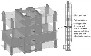
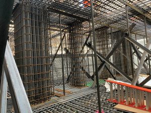
The main lateral load-resisting system is a central shear wall core. As is normally the case, shear walls around an elevator core require openings to allow for the elevator lobby at nearly all floors. Residential towers tend to maintain the least floor-to-floor height possible, and the underside of slabs is finished to create the ceiling in the apartment below. At the same time, links above the elevator core openings are necessary for the core to act as closely as possible to a tubular spine extending up the building. The conflict of limited depth available for the link beams and the very high loads passing through those link beams presents a challenge. In addition, the beams obstruct mechanical systems that normally require access into the core area.
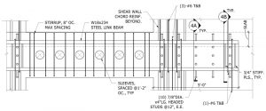
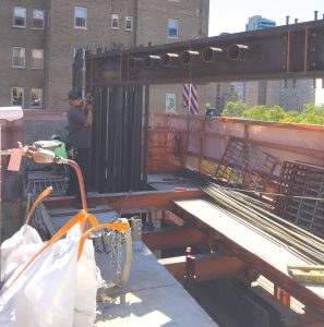
Balancing these challenges led the design team to use steel beams embedded in the concrete link beams to resist high shear and moment loads imposed on those beams in some shear walls. This involves considering the transfer of forces from one wall, across the opening through the beam, and back to the wall on the other side of the opening. While the governing loads for these link beams are wind-induced, the American Institute of Steel Construction’s (AISC) Seismic Design Manual section on composite coupling beams and other research was useful in guiding the design of these beams. Complex details were required. Careful coordination down to each individual pipe sleeve was required and considered in the beam design to accommodate the MEP systems that pass through the beams.
Walking Column
A walking column is a term used to describe the condition where the column above is not located directly above the column below. This creates an offset and eccentric load on both columns, resulting in horizontal forces at each end of the column that must be resolved into the floors above and below.
For this project, there were conflicting desires. The local community desired a limit to the height of the building. The developer wanted to maximize the FAR (floor-to-site-area ratio) to that permitted by Code, yet a portion of the site was occupied by a three-story historic building that would be preserved. The floors above the height of the historic structure were expanded to the west to capture additional floor area, requiring the edge columns to be located outboard of the locations below. A transfer beam was considered, but the added depth of structure would “grow” the building taller. The team settled on walking the columns in four successive floors to achieve the transferred column location in the more than 40 floors above.
There are considerable horizontal loads at the top of the uppermost and bottom of the lowermost columns. This is particularly an issue where there are more than 40 floors of structure above. These horizontal forces must be resolved in the design of the floor diaphragms and drag struts to provide a load path to the concrete core. In tension strut locations, mechanically terminated tension drag struts were designed to drag these forces into the core. In areas outboard of the core, similar drag struts were designed, and then supplemental diaphragm reinforcing transferred the forces into the core.
Concrete Strength
High-strength concrete was required to accommodate the design of this structure. Based on experience, available data in the local supplier market, and extensive laboratory testing, these strengths were pre-validated early in the design process. Laboratory testing submissions were specified to demonstrate strength and a prescribed modulus of elasticity for concrete to be used in columns and shear walls. Shear wall and column concrete ranged from 14,000 psi at lower levels in the building to 8,000 psi at upper levels. Floor slabs required 8,000 psi at the lower floors to meet ACI 318 Building Code Requirements for Structural Concrete, requirements for load transmission through floors, and avoid placing higher strength concrete at the column/slab interface to control puddling. Puddling requires placing high-strength column concrete within a two-foot zone beyond the column/slab interface. This can be difficult to control during concrete slab placement. Floor slabs required 6,000 psi concrete at upper floors where column concrete strengths were lower. A 56-day strength testing procedure was specified to accommodate the slow rate of hydration.
The cooperation between all members of the design and construction team is critical to the success of any project. Understanding the local concrete subcontractor and the material market proved a valuable asset for the design team, resulting in a smooth and efficient construction process.■
Project Team
Owner/Developer: Southern Land Company, Nashville, TN
Structural Engineer: The Harman Group (now IMEG), Philadelphia, PA
Architect of Record: Solomon Cordwell Buenz, Chicago, IL
MEP Engineer: Bala Consulting Engineers, King of Prussia, PA
Geotechnical Engineer: GeoStructures, Inc., King of Prussia, PA
Wind Consultant: RWDI, Guelph, ON (Canada)
Construction Manager: Hunter Roberts Construction Group, Philadelphia, PA