
Armory Park Elderly Housing Project
The tallest post-tensioned masonry building in the United States was completed in 2013 in Sentinel Plaza, an Independent Senior Housing Development, in Tucson, Arizona. The new building is six stories high with 139,000 square feet and 143 units (Figures 1 and 2).
Within the Sentinel Plaza Development was an existing building called Armory Park. Armory Park, a HUD 202 building, had been determined to be outdated and needed to be replaced. SHG (Senior Housing Group), using Arizona Low Income Tax credits, took on the task of building the replacement building, which is also called the Armory Park building.
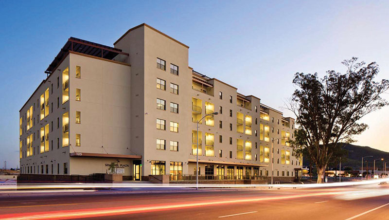
Figure 1. Elevation.
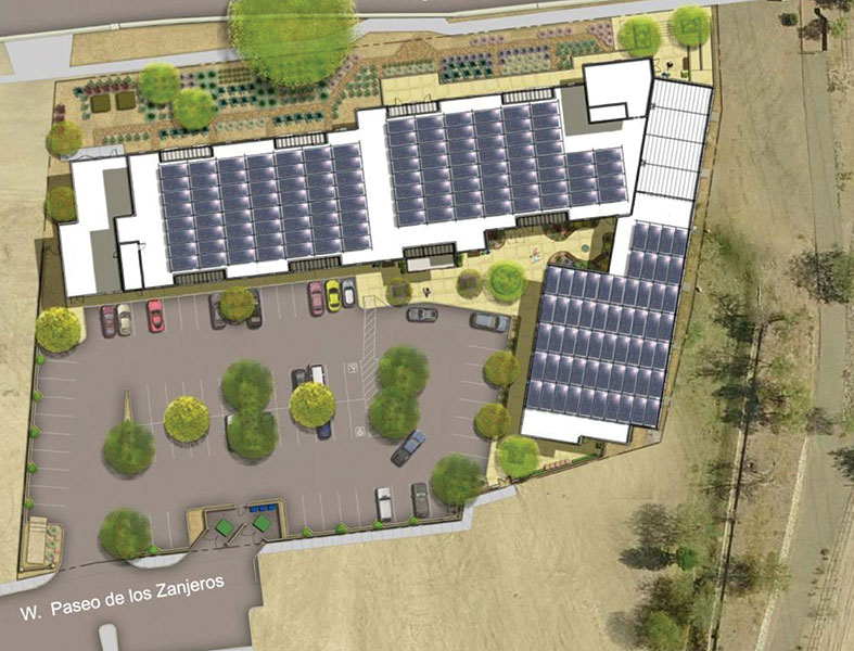
Figure 2. Plan view.
The Sentinel Plaza Development requires sustainable architecture design for the buildings in the development. Armory Park was designed to meet LEED (Leadership in Energy and Environmental Design) Gold standards. Roof mounted solar modules offset 75% of the common area’s electrical loads. Landscaping uses drip irrigation, low water use native plants and passive water harvesting. High efficiency mechanical units, low water use plumbing features and high performance windows were used.
As a part of achieving the LEED Gold, the exterior walls were required to contribute to the energy savings by having an average R value of 16. Four exterior wall systems were evaluated/considered:
Masonry Walls
Pros
- Masonry is a common exterior wall system in Tucson, AZ.
- The exterior masonry walls can be the Post-Tensioned Masonry Wall System and achieve an R = 19 for 8-inch thick CMU (concrete masonry unit) walls.
- Grout and rebar can be used in masonry for detailing as required by structural calculations.
- Masonry is a very durable exterior wall surface.
Cons
- Masonry is not viable as the exterior wall unless a significant R value can be achieved with the masonry wall or with furred out walls with insulation.
Concrete Walls
Pros
- Concrete is a common exterior wall system in Tucson, AZ.
- Concrete is a very durable exterior wall surface.
Cons
- Concrete walls cannot achieve an R of 19 unless the walls are sandwich panels with Styrofoam/ high density polystyrene in the middle of the concrete wall, or if walls are furred out and insulation is used in the furred out walls.
Steel Studs
Pros
- Steel studs are a common method to build exterior walls in Tucson, AZ.
- Insulation can be placed between the steel studs to achieve the required wall R value.
Cons
- The steel studs allow for thermal transfer of heat/cold from the exterior to the interior through the steel webs of the steel studs.
- The exterior material (stucco over gypsum board) on the steel stud walls is not as durable as masonry or concrete exterior walls.
Insulated Concrete Forms (ICF) Walls
Pros
- ICF walls can provide the wall R value required.
Cons
- ICF walls are not as common as masonry, concrete, or steel stud exterior walls in Tucson, AZ.
- The exterior material (stucco over the insulating foam form) is not as durable as masonry or concrete walls.
The original LIHTC (Low Income Housing Tax Credit) application included ICF as the load bearing & insulated exterior wall system. The general contractor (W.E. O’Neil) suggested post-tensioned masonry as an alternate system for several reasons: durability, ease of construction, and similar insulating characteristics. Additionally, the CMU met LEED requirements for local sourcing. After an evaluation of the relative cost, schedule impacts, and LEED requirements, a post-tensioned masonry wall system was chosen to be used as the exterior wall (Figures 3, 4 and 5).
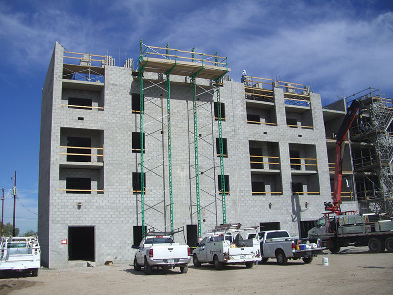
Figure 3.Under construction.
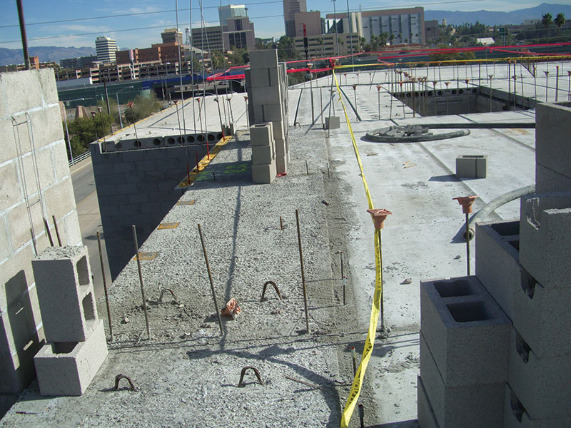
Figure 4. Plank floor with CMU bearing walls.
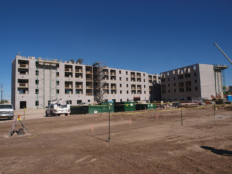
Figure 5. Building under construction.
Superlite Block (an Oldcastle Division in Phoenix, AZ) developed the “Post-Tensioned Masonry Wall System” (Integra) in 1984. The post-tensioned system was developed in order to provide a structural masonry wall with significant R value. Superlite was issued an ICBO report in 1991, which is now ICC Legacy Report ER-4845. (This ICC approval preceded the development of the Prestressed Masonry chapter in the Building Code Requirements for Masonry Structures (ACI 530/TMS 402/ASCE5) and is still being used. The ACI 530 is available for prestressed masonry design and is used by most designers.)
The post-tensioned system can be designed using either Allowable Stress Design (ASD) or Ultimate Strength Design (USD) as outlined in the ICC Legacy Report. ASD was chosen for this project, as ASD has been used in the majority of Integra projects done to date. The design procedure used follows the simple design principles: P/A and M/S. The allowable stresses in the Legacy Report are based on full scale load tests done in 1991 at the NCMA (National Concrete Masonry Association) Lab in Herndon, VA. The allowable stresses are as follows:
Axial Compression – 360 psi
Axial Tension – Not Allowed
Bending Compression – 540 psi
Bending Tension – 22 psiI
Shear – 59 psi
The system uses 7/16-inch diameter smooth steel rods as the post-tensioned rods (PT rods) with Fy min = 60 ksi. The post-tensioned rods are tensioned to 7,400 pounds and the usable tension in each rod is 5,000 pounds taking into account the losses. See Figure 6 for the CMU units used.
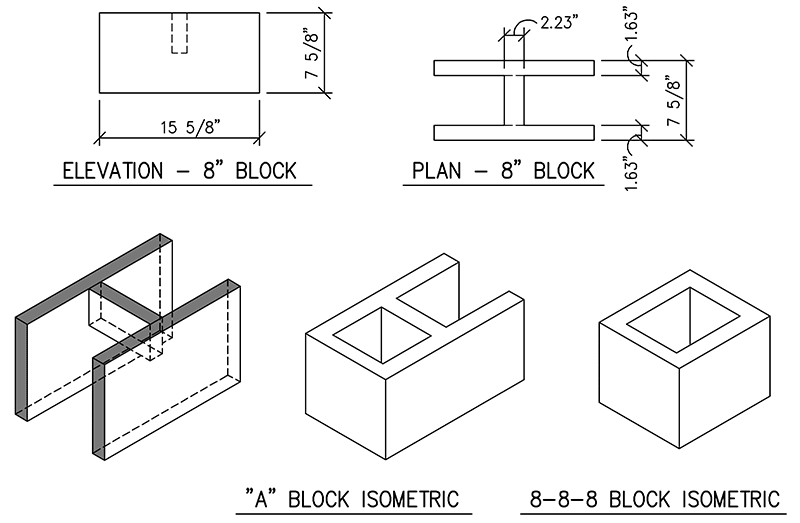
Figure 6. Detail of standard CMU units.
The post-tensioned system was designed initially to be used as an exterior residential wall. However, it has also been used in many commercial projects like the Armory Park project. The main differences, in residential versus commercial design, are the magnitude of the loads, the height of the walls and the size of wall openings. There have been some residential projects where all of the masonry walls have been post-tensioned, meaning no grouted cells were required. Those structures can use the total R = 19 for an 8-inch thick wall. Most residential and commercial post-tensioned projects require some locations in the wall with solid grouting or solid grouting with rebar, therefore an average R value can be computed. For example, wherever there is a need for a bolted connection of a ledger to a wall, the bolts are placed in a solid grouted bond beam with two pieces of rebar. Wherever there is an opening large enough that the post-tensioned system won’t work, a reinforced solid grouted jamb is designed.
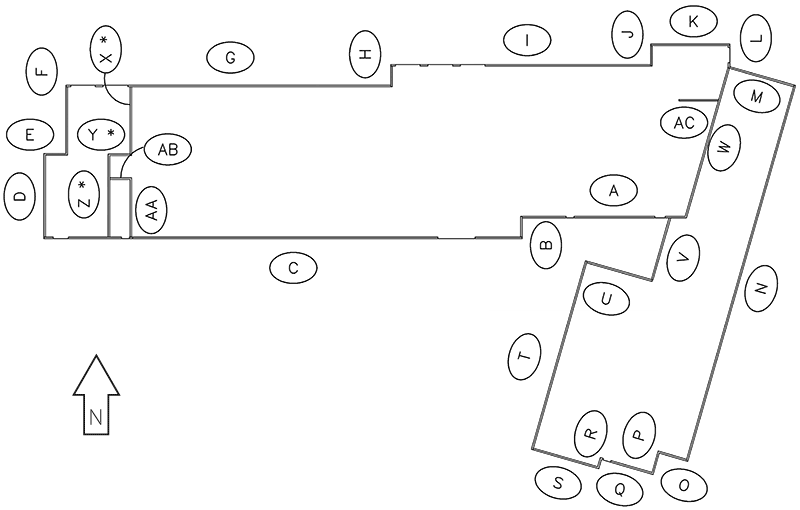
Figure 7. Key plan of wall elevations.
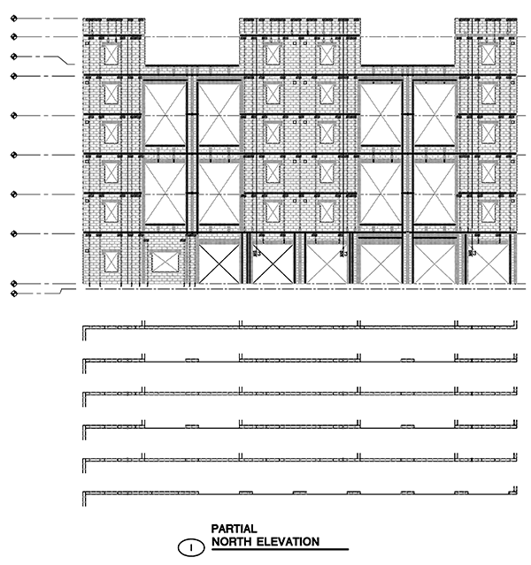
Figure 8. Partial north elevation “I”.
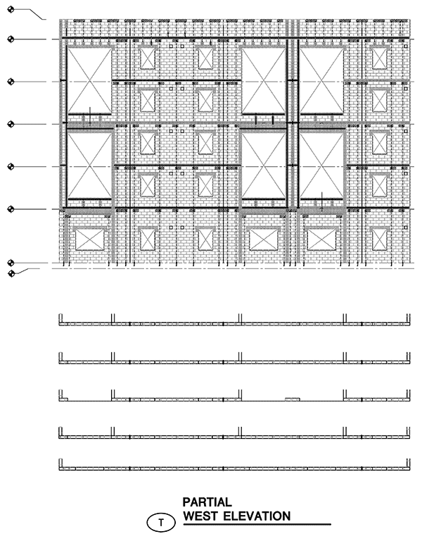
Figure 9. West elevation “T”.
Structural Factors
- The seismic response modification coefficient R for ordinary reinforced masonry walls is 3.5 versus 1.5 for the R of ordinary prestressed masonry walls (Reference Table 12.2-1 ASCE 7-05). Discussion – The seismic lateral loads were larger than the wind lateral loads, so using an R of 1.5 versus an R of 3.5 increased the lateral loads on the building. The increase in lateral loads turned out not to be a significant design concern because the amount of masonry walls available was adequate for the R = 1.5 and the interior party walls were reinforced masonry, not post-tensioned.
- There were concerns that the masonry contractor would have difficulty determining where the post-tensioned CMU occurred versus the conventionally reinforced CMU. Discussion – The post-tensioning structural engineer decided to provide elevations of all the exterior walls. The elevations showed every concrete masonry unit and, through the use of different shading and hatching, the post-tensioned CMU could be distinguished from the conventionally reinforced CMU. Every post-tension rod was shown, every piece of re-bar was shown and grout locations were shown (Figures 7, 8 and 9).
- Post-tensioning didn’t work at all of the exterior walls. Discussion – The post-tensioning system was used for the entire six stories at the non-bearing walls. At the bearing walls, the compression due to the vertical loads and the post-tension rods compressing the walls was significant. Therefore, only the top two floors are post-tensioned at these locations.
- Detail coordination between building engineer (SEOR) & the Post-tensioning Designer. Discussion – Because post-tensioning is often treated as a deferred submittal in the design process, the Structural Engineer of Record has typically already completed the structural detailing prior to the post-tensioning being designed. The structural details may show conventional masonry or they may dash in the post-tensioning masonry walls to be designed by others. In the case of Armory Park, the completed details by the SEOR showed the post-tensioning masonry dashed in, so the design team was able to base the connection details off of the structural details and include the information required for the post-tensioning construction. This coordination allowed the details to appear consistent between the structural drawings and post-tensioning drawings, and each consultant was able to review the details and verify acceptability prior to being finalized (Figures 10, 11, 12, and 13).
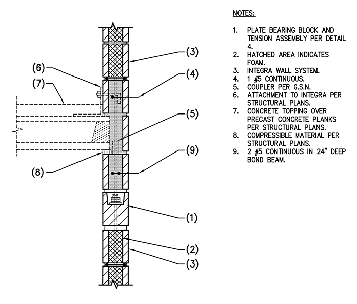
Figure 10. Detail of precast concrete at post-tensioned wall: bearing.
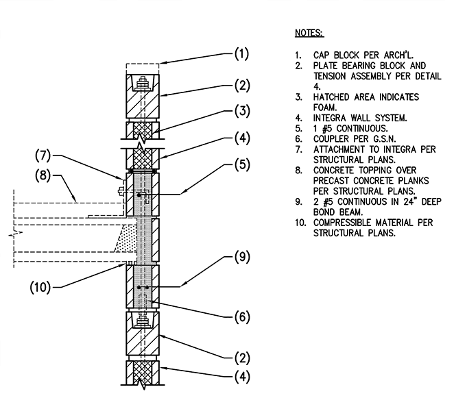
Figure 11. Detail of precast concrete at post-tensioned wall with parapet: bearing.
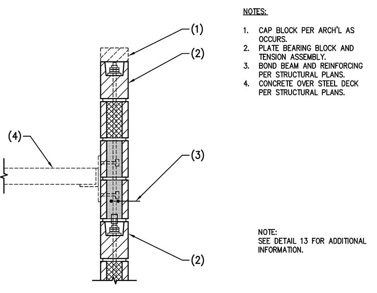
Figure 12. Detail of concrete over steel deck at post-tensioned wall.
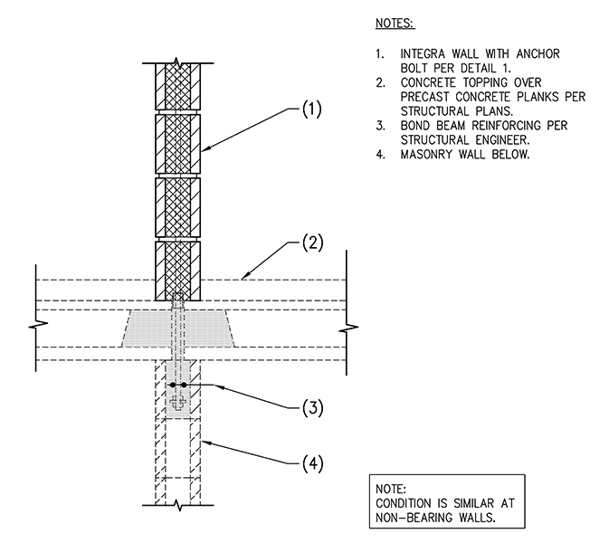
Figure 13. Detail of post-tensioned wall above conventional CMU wall.
Quest Energy Group provided the energy modeling services for the building. TestMarcx Commissioning Solutions provided commissioning for LEED for Homes Midrise credits EA Pre-requisite 1.2 (Energy & Atmosphere Optimize Energy Performance: Testing and Verification) and EQ 12.1 and 12.2 (Indoor Environmental Quality: Prerequisite And Enhanced Compartmentalization of Units). Pima County Development Services Green Building Program served as the LEED for Homes Provider and Green rater, and also provided Durability Management Verification (credit ID 2.3). The post-tensioned masonry system contributed to the following LEED midrise points:
- ID 2.1, 2.2 and 2.3 (Quality Management for Durability)
- ID 3.1 (Innovation and Design for exemplary performance in SS 5 Pest Control)
- SS 5 (Nontoxic Pest Control)
- EA 1.1 and 1.3 (Minimum and Optimize Energy performance)
- MR 2.2 (local production, exterior wall)
Throughout construction, all lines of communication ran through the architect, so that all consultants would remain coordinated. Because of the thorough coordination effort during the design process, field coordination issues were kept to a minimum. With this practice in place, the award-winning Armory Park project was successfully completed ahead of schedule.▪
Project Team
Owner: Senior Housing Group, Tucson, AZ
Structural Engineer of Record: Schneider & Associates
Architect: Lizard Rock Designs, Tucson, AZ
General Contractor: W.E. O’Neil, Phoenix, AZ
Masonry Contractor: Hobbs Masonry, Phoenix, AZ
Masonry Supplier: Superlite Block , Phoenix, AZ
Post-tensioning Design Structural Engineer: Caruso Turley Scott Inc.