
In terms of structural concrete masonry unit (CMU) construction, the predominant unit sizes are nominally 8-inch and 12-inch-wide units. However, with rising material costs, 6-inch-wide units are ideal for interior and exterior wall construction depending on wall heights and design loads.
In terms of interior partition walls, ungrouted and unreinforced CMU wall construction is often the most cost-effective solution compared to other building systems. In addition, CMU construction provides superior fire resistance and sound transmission performance. Unreinforced masonry partition walls are typically designed for lateral forces prescribed under the International Building Code (IBC) and the American Society of Civil Engineers’ Minimum Design Loads and Associated Criteria for Buildings and Other Structures (ASCE 7).
These lateral loads typically include a minimum horizontal load specific to interior walls and partitions included in IBC Section 1607.15.
IBC Section 1607.15 Interior walls and partitions. Interior walls and partitions that exceed 6 feet (1829 mm) in height, including their finish materials, shall have adequate strength and stiffness to resist the loads to which they are subjected by not less than a horizontal load of 5 psf (0.240 kN/m2).
Relative to the partition lateral load, recommendations are provided in The Masonry Society’s (TMS) Strength Design of Masonry publication. “There is not a direct strength load combination that addresses the partition load. Use 0.9D for flexural tension to be consistent with other strength load combinations where the dead load is acting as a ‘resistance’ and use 1.6 as a load factor for out-of-plane partition load (live load).”
Based on this minimum interior wall and partition horizontal load, a maximum wall height is calculated based on the mortar type specified and the density of the masonry units. The Masonry Society standard TMS 402-16, Building Code Requirements for Masonry Structures, includes values for the modulus of rupture (fr) of masonry based on mortar type, the direction of flexural tensile stress, and the masonry type in Table 2.5-3. For interior walls and partitions, the maximum wall height is typically controlled by flexural tension, which can be calculated as the difference between the axial compressive stress and the bending stress, and then compared to the factored design flexural tension stress:
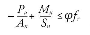
where:
- Pu = factored axial load at the critical section
- An = net area (24.0 in2/ft for ungrouted 6-inch CMU)
- Mu = factored moment at the critical section
- Sn = net section modulus (43.3 in3/ft for ungrouted 6-inch CMU)
- φ = strength-reduction factor (0.6 for unreinforced masonry subject to combinations of flexure and axial load)
- fr = modulus of rupture (Table 2.5-3)
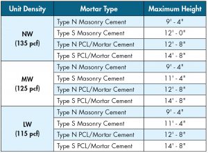
For walls spanning vertically and having the net flexural tension normal to bed joints, 6-inch ungrouted interior CMU walls and partitions in low seismic areas, which are controlled by the minimum 5 psf (0.240 kN/m2) horizontal load, have maximum wall heights presented in Table 1. These wall heights are based on the wall having pinned support conditions at both the base and top of wall conditions.
For interior walls and partitions, out-of-plane seismic forces must also be considered. Out-of-plane seismic forces are determined following Chapter 13 of ASCE 7.
ASCE 7 Section 13.3.1.1 Horizontal force. The horizontal seismic design force (Fp) shall be applied at the component’s center of gravity and distributed relative to the component’s mass distribution and shall be determined in accordance with Eq. (13.3-1):
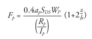
where:
- Fp = seismic design force
- SDS = spectral acceleration, short period, as determined from ASCE 7 Section 11.4.5
- ap = component amplification factor (1.0 for unreinforced masonry partitions in ASCE 7 Table 13.5-1
- Wp = wall weight
- Rp = component response modification factor (1.5 for unreinforced masonry partitions in ASCE 7 Table 13.5-1)
- Ip = component importance factor
- z = height in the structure of the partition wall
- h = average roof height
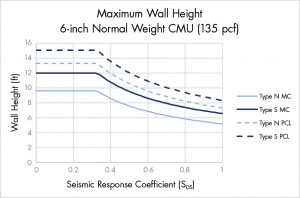
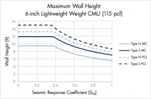
Conservatively, a masonry wall can be assumed to have z equal to h. As stated in Strength Design of Masonry, “The value for Ip is permitted to be taken as 1.0 unless the interior wall or partition contains highly toxic, explosive, or hazardous substances, or is part of an egress stairway, or is in a Risk Category IV structure and its failure could impair continued operation of the facility, in which case Ip = 1.5.” Based on these assumptions, the maximum wall height can be calculated. The results are presented in Figure 1 through Figure 3.
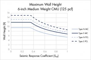
These figures are based on Ip = 1.0 and would need to be modified if a higher importance factor were required. Additionally, the maximum wall height in each figure has been limited to the maximum wall height based on the minimum horizontal load prescribed by Section 1607.15 of the IBC.
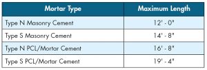
For interior walls and partitions designed to span horizontally between supports, such as intersecting walls or pilasters, maximum horizontal spans can be calculated similarly and are based on an fr corresponding to tensile stress parallel to bed joints provided in TMS 402-16 Table 2.5-3. For interior walls and partitions where the 5 psf (0.240 kN/m2) controls, maximum horizontal spans are presented in Table 2.
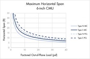
A maximum horizontal span can similarly be calculated based on mortar type and a factored out-of-plane load (Figure 4).
For exterior walls, the capacity of a 6-inch CMU wall can be calculated based on the strength design provisions in Chapter 9 of TMS 402. Typically, a complete interaction diagram is developed for a wall to ensure all factored loads are within the capacity envelope. However, for nonbearing, reinforced CMU walls, designers can conservatively neglect the masonry self-weight and solve for the pure flexural capacity of the wall. To solve for the flexural capacity, first, use the strength design provisions to solve for the depth of the equivalent compressive stress block (a). If a is less than the face shell thickness (1-inch for a 6-inch CMU), it can be analyzed as a solid section. If a is less than the face shell thickness, then the required area of reinforcement can be solved directly. Equations for a and the required reinforcement area are included in the Strength Design of Masonry and presented below.
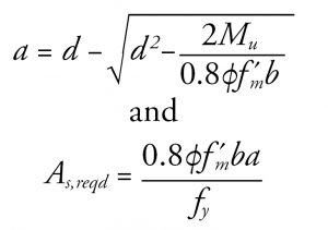
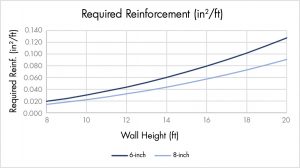
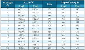
For comparison, the required reinforcement areas were calculated for both 6-inch and 8-inch CMU walls based on a 30 psf (1.44 kN/m2) factored out-of-plane load, and the results are presented in Figure 5. As shown, the required reinforcement is greater for 6-inch CMU walls, which is expected, and the values diverge as wall height increases.
In terms of reinforcement spacing, the required spacing of a #5 vertical bar is provided in Table 3. The reinforcement spacing was limited to a maximum of 120 inches (304.8 cm), assuming the wall is an ordinary reinforced masonry shear wall and subject to seismic detailing requirements.
Wall Weights
Specifically, in higher seismic design categories, dead load impacts the lateral force on the building structure and the design of the lateral force-resisting system. Using 6-inch CMU in lieu of an 8-inch CMU for interior wall construction decreases the weight of the wall by an average of 23%. Representative CMU wall weights are presented in National Concrete Masonry Association’s (NCMA) publication TEK 14-13B. Beyond the reduction in the design lateral force, the lower weight can impact foundation design. For interior walls specifically, thickened slab sections can potentially be used in place of wall footings, allowing for more efficient project scheduling.
Fire Resistance Ratings
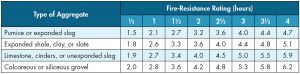
Methods for determining fire resistance ratings are provided in Section 703.3 of the IBC. Specific to masonry construction, fire resistance ratings are typically calculated following the procedure presented in Section 722 of the IBC. As stated in IBC Section 722.3.2 and specific to concrete masonry walls, the fire-resistance rating of walls and partitions shall be determined from Table 722.3.2. The rating shall be based on the equivalent thickness of the masonry and type of aggregate used, and minimum equivalent thicknesses are provided in IBC Table 722.3.2. For brevity, the minimum equivalent thickness values are provided based on ½-hour increments in Table 4 but can be found based on ¼-hour increments in the IBC.
For partially grouted walls where the unfilled cells are left empty, the equivalent thickness for calculation of the fire-resistance rating is equal to that of an ungrouted unit. Values for the equivalent thickness of typical hollow units are presented in NCMA TEK 07-01D. For a typical 6-inch wide hollow unit, the equivalent thickness provided by NCMA is equal to 3.1 inches (7.9 cm). Thus, a 6-inch partially grouted or ungrouted wall achieves a 1-hour fire-resistance rating depending on the type of aggregate used. Depending on the mix design and geometry of the unit, higher fire-resistance ratings may be possible.
The equivalent thickness of a 100% solid unit or solid grouted unit is equal to the actual thickness. Additionally, IBC Section 722.3.1.4 allows for the equivalent thickness to be equal to the actual thickness of the unit if the units are filled with loose-fill materials specified in that section. Thus, for a 6-inch unit, either grouted solid or filled with an approved material, the equivalent thickness would be equal to the specified thickness of 5.625-inches (14.3 cm). Therefore, depending on the aggregate used in the manufacture of the CMU, a 6-inch CMU wall, either grouted solid or filled with an approved material, could achieve a 3-hour fire-resistance rating.
Sound Transmission Class
Masonry construction exhibits superior performance in terms of sound transmission, which is especially useful in environments such as mixed-use and residential buildings. Depending on owner requirements, a sound transmission class (STC) rating of 50 is required specifically for dwelling units and sleeping units separated from adjacent occupancies. Specifically, the IBC has sound transmission requirements presented in Section 1206.
1206.2 Airborne Sound. Walls, partitions, and floor-ceiling assemblies separating dwelling units and sleeping units from other or from public or service areas shall have a sound transmission class of not less than 50, or not less than 45 if field tested, for airborne noise where tested in accordance with ASTM E90.
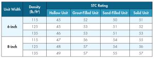
In masonry construction, STC ratings can be estimated based on testing performed by NCMA and calculated values presented in TEK 13-01C. Sample results are presented in Table 5, showing that, typically, 6-inch CMU walls will have an STC rating of 3 to 4 less than the corresponding 8-inch CMU wall. For a range of densities, STC ratings for 6-inch walls comprising hollow units vary from 45 to 46.
If 6-inch CMU walls are used to separate dwelling units and sleeping units from the areas noted in the IBC, there are two common options for increasing the STC rating to exceed 50:
- Add drywall to one or both sides of the CMU wall, potentially including a furring space with sound-absorbing material.
- Fill the units with grout or sand or use solid units.
As shown, the difference between the performance of 6-inch and 8-inch CMU walls in terms of STC ratings is minimal. Additional recommendations and considerations are presented in NCMA TEK 13-01C.
Summary
Especially for interior walls and partitions, 6-inch CMU wall construction can be economical and schedule-friendly. In addition, 6-inch CMU wall construction provides the following advantages:
- It reduces the wall thickness by 2 inches (5.0 cm), adding to the usable floor square footage, especially on larger projects such as school construction.
- It can achieve a minimum 1-hour fire-resistance rating, either partially grouted or ungrouted, and a minimum 3-hour fire-resistance rating if grouted solid or filled with an approved material.
- It has a similar performance in terms of STC ratings when compared to an 8-inch CMU wall.
- It reduces wall dead load by approximately 23%, reducing the design lateral force and allowing for smaller foundations, including thickened slab construction.
- Based on contractors polled for this article, an ungrouted 6-inch CMU partition wall provides approximately 3% to 5% cost savings per square foot compared to an ungrouted 8-inch CMU partition wall. Compared to a partially grouted 8-inch CMU partition wall, an ungrouted 6-inch CMU partition wall provides approximately 10% to 20% cost savings per square foot.
6-inch CMU provides an excellent solution for mixed-use, residential, and school projects, specifically for partition wall construction. When specifying CMUs on your next project, verify availability with local contractors and suppliers and discuss options for corner details when using 6-inch CMU.■
References
(2018). International Building Code. Falls Church, VA: International Code Council.
(2016). Minimum Design Loads for Buildings and Other Structures. Reston, VA: American Society of Civil Engineers.
(2020). Strength Design of Masonry. Denver, CO: The Masonry Society.
(2016). Building Code Requirements and Specification for Masonry Structures. Denver, CO: The Masonry Society.
Concrete Masonry Wall Weights, TEK 14-13B. Reston, VA: National Concrete Masonry Association.
Fire Resistance Ratings of Concrete Masonry Assemblies, TEK 07-01D. Reston, VA: National Concrete Masonry Association.
Sound Transmission Class Ratings for Concrete Masonry Walls, TEK 13-01C. Reston, VA: National Concrete Masonry Association.