
Steel sections can be used as columns, beams, and struts to resist axial forces (tension/compression), moments, and shears. They may come in the form of open sections (such as ASTM A992 – Wide Flange W-shapes beams/S-shapes beams) or closed sections (such as Hollow Structural Section [HSS] tubing).
Physical dimensions and weights designate most steel sections, i.e., American Wide flange shapes are designated by depth of section x weight per unit length (e.g., W24x76), and British Universal Beam shapes are designated by depth of section (mm) x width of a section (mm) by weight (kg/m) (e.g., UB610x229x113). On-site, it is also easy and convenient to measure a section’s physical dimensions of depth, width, and thickness. Sometimes, steelwork designers must quickly size up a section or estimate section capacities without immediate access to comprehensive section properties or code equations. This is where rules-of-thumb become helpful. This article summarizes a few rules-of-thumb to evaluate steel section capacities.
Section Properties
When evaluating a section’s capacity, the most relevant section properties are the cross-sectional area, the moment of inertia, and the radius of gyration. A cross-sectional area is required for tension and compression capacity, the moment of inertia for moment capacity, and the radius of gyration for buckling resistance.
Since the density of steel is 490 lb/ft3 (7850 kg/m3), the cross-sectional area of section (A) can be derived by dividing the weight per unit length by the density.
Similarly, the moment of inertia (I) and radius of gyration (r)can be correlated to section sizes (depth and width) and weight per unit length.
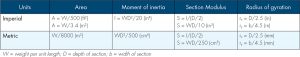
For ease of remembering, these can be approximated using the expressions in the Table. For example, a W24×76’s cross-sectional area is 76/3.4 = 22.4 in2.
The approximate moment of inertia WD2/20 can be obtained by summing up flange area multiplied by the square of distance from the centroid and assuming a proportion of the total cross-sectional area lies within the flanges. For W-shape sections, by assuming a ¾ proportion, a conversion factor of 20 is obtained which corelates well with the actual moment of inertia. For British Universal Beam (UB) sections, there is more area in the web and the moment of inertia may be closer to WD2/25.
Axial Load Capacity
The axial load can be in tension or compression, acting axially along the longitudinal direction of a member. Load-carrying capacity is typically calculated using the stress multiplied by the cross-sectional area, with appropriate load, resistance, and safety factors applied.Compression members have an added complication in dealing with slenderness where buckling becomes the governing failure criteria instead of crushing.
One common rule of thumb for compressive strength is: ½ the strength of materials (0.5 × yield strength, Fy) could be used for structural design for column members, i.e., members that are above the ground where they can be seen, and ⅓(0.3Fy) for piles, i.e., members that are below the ground where they are out of sight.
Since the 1800s and 1900s, when designing using allowable stresses, the ultimate (maximum) strength has to be reduced by a safety factor to arrive at a stress used for design. For example, mild steel having an ultimate strength of 65 kips per square inch (ksi) (448 megapascals, MPa) would have an allowable compression stress of 16.25 ksi (112 MPa) using a factor of safety of 4 (i.e., 0.25Fu). This seemingly high factor of safety is because ultimate strength, Fu, is used, which is higher than yield strength. Therefore, upon reaching yield, the material would enter into the plastic range and no longer be elastic.
In modern times, allowable stress design (ASD), governed by the American Institute of Steel Construction (AISC) Specification code, stipulates allowable stress for tension members to be 0.6Fy (yield stress) or 0.5Fu (tensile strength) on the gross and net effective area, respectively.
When steel sections are used as piles (e.g., H-piles), the allowable stress is ϕ(ecc)Fy/(LF), where ϕ, ecc, and LF are the stress-reduction factor, eccentricity, and load factor, respectively. Load factor is taken as 2, which is in line with the super-structure member safety factor. Due to the uncertainties involved in underground piles, two additional factors were introduced: stress reduction and eccentricity. Φ and ecc are 0.85 and 0.7 respectively, which gives a product of 0.595. Together with a load factor of 2, the allowable stress for piles becomes 0.3Fy in accordance with Federal Highway Association publications.
Another common rule of thumb for the working compression load capacity of steel sections is: 1 kilogram (kg) of steel carries one ton (using a unit conversion of 1 ton = 1000 kg = 10 kilonewton, kN) of load. This rule of thumb is meant for British Universal Beam and Column (UB and UC) sections for S275 MPa (≈Grade 36) steel used as piles and therefore comes with a safety factor of 3. For example, a UB610x229x113 (mm × mm × kg/m) section would have a working load of 1130 kN and a nominal yield capacity of 3390 kN. This estimate is only for a short column without considering slenderness or buckling. The capacity for S355 MPa (≈Grade 50) steel can be estimated by simple proportion (i.e., applying a 355/275 factor).
In US customary units, the conversion factor is 8.8 (=1/490 pcf × 144 in2 × 50 ksi × 0.6) for A992 steel (Fy = 50 ksi). Therefore, the available axial compressive strength of a Grade 50 W14×109 section can be approximated as 109×8.8 = 959 kips.
To account for buckling, which must be considered, the slenderness ratio (c) = (Lc/r), which is the effective length (Lc) divided by the least radius of gyration (r) (the weak axis). For example, the legacy British Standard BS449:1948, The use of structural steel in building, used an allowable column compressive stress of 124 MPa (18 ksi) for a slenderness ratio of c = 20, which decreases to 25.9 MPa (4 ksi) for a slenderness ratio of c = 180. This is almost equivalent to a 15 MPa (2 ksi) decrease in stress capacity for every 20-increment increase in slenderness ratio (c) starting from c = 20 (Figure 1). Note that this curve is valid for steel with an ultimate tensile strength of 56 to 66 ksi.
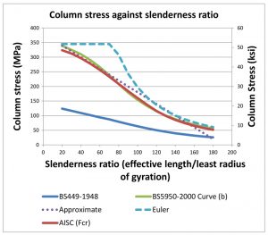
When we compare two modern codes, namely the American Institute for Steel Construction AISC 360, Specification for Structural Steel Buildings, and the British Standard BS5950-2000, Structural use of steelwork in building, we can see that the column buckling curves for Fy = 50 ksi (345 MPa) steel are very similar. These real-life design curves provide lower column stresses than the theoretical Euler curve, where eccentricities and imperfections are not accounted for. The deviation from the Euler curve is most pronounced at the curve transiting from buckling to the crushing failure mode. It should be noted that the yield strength of the material does not play a part in buckling. Changing the yield stress only affects the crushing stress portion of the curves where the slenderness ratio is at relatively lower levels. Besides the usual flexural buckling, designers should also be mindful that torsional or flexural-torsional buckling might become critical, especially for certain sections (e.g., asymmetric, singly symmetric, cruciform, or built-up sections, etc.). The legacy British Standard BS449-1948 curve is based on allowable column stress, which means that it is already factored. Readers need to be mindful of the various factors required by different codes and adapt accordingly when using simplified rules.
Another valuable formula to evaluate buckling capacity is the Rankine formula:
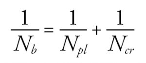
where:
Nb = buckling capacity
Npl = Fy × A where Fy = yield stress and A = area (plastic limit)
Ncr = π2 EA/c2 where E = Young’s modulus and A = area (critical Euler curve)
This formula is essentially an equation form of the combined interaction curve for crushing and buckling failure modes. The plastic limit term is constant for a particular section. At low slenderness ratios, 1/Ncr becomes negligible, and the governing failure mode is crushing. Conversely, when the slenderness ratio is high, 1/Ncr becomes the dominant term, and the governing failure mode becomes buckling.
Moment and Shear Capacity
Moments and shear forces often co-exist together in a structural member in bending. Modern design codes contain detailed procedures in dealing with moment and shear for a wide variety of circumstances. However, in its most basic form, moment capacity can be expressed as a product of yield stress and elastic section modulus.
Mn = FySx
The elastic section modulus is related to a section’s moment of inertia, which can be estimated from the section’s dimension and weight using WD/10 from (WD2/20)/(D/2). Designers should be aware that compact sections, which allow whole section yielding, may stretch the envelope further by adopting the plastic modulus in place of the elastic modulus. The shape factor, a ratio of plastic modulus against the elastic modulus, may range from 1.1 (I-beams) to 1.5 (rectangle), depending on the cross-sectional geometry. Beams without lateral restraint see a compromised moment capacity due to lateral-torsional buckling. In addition, there are also other aspects to consider, such as local buckling. High shear coincident with moment can reduce a section’s moment capacity. However, such cases are rare in practice, as most beams are designed as simply supported instead of continuous.
Allowable shear capacity is 0.6FyAv, where the shear area Av is the area of the web (depth times web thickness). Most column and beam section web thicknesses can vary considerably, so it is not easy to generalize. Nonetheless, for many shallower W-sections (less than 20 inches), 20% to 50% of cross-sectional area is assumed to fall within the web. The proportion becomes 30% to 50% for the deeper W-sections (deeper than 20 inches).
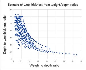
The reader should note that the depth-to-web-thickness ratio for W-sections can vary quite widely from below 20 to above 60 (Figure 2). Nonetheless, it is still possible to get a rough estimate from the weight-to-depth ratio (W/D), especially for W/D greater than 10. For example, if the W/D ranges from 10 to 25, the depth to web-thickness ratio is likely to range from 10 to 30. The higher the weight, the more likelihood of a thicker web and hence the inverse relation.
In many typical steel beam designs, moment is likely to be critical instead of shear. As an illustration, consider a simply supported beam of length L under uniform loading, w. The maximum moment is wL2/8 at midspan, and the maximum shear is wL/2 at the support. For any given w, the numerical value of the moment is equal to shear when span L is equal to 4. Beyond 4, a moment increases exponentially compared to shear when L increases due to the squaring effect of L. Inspecting a typical section capacity table for moment and shear resistance, it can be generalized that moment capacity will be critical for many typical cases (see below).
Moment vs. Shear Criticality Examples
S275 UB610x229x113 has a moment and shear capacity of 869 kNm and 1090 kN respectively. Applying the simple rules gives:
Moment of inertia = 113×6102/500 = 84095 cm4
Elastic section modulus = 84095/(61.0/2) = 2757 cm3
Moment capacity = 275×2757000 = 758 kNm
Shear capacity = 610/50×610×275×0.6 = 1228 kN
An ASTM A992 W12x30 (Fy = 50 ksi) has nominal moment (Fy*Z) and shear capacity (0.6*Fy*Aw) of 180 kip-ft and 96 kips, respectively. Applying the simple rules gives:
Moment of inertia = 30×122/20 = 216 in.4
Elastic section modulus = 216/(12/2) = 36 in.3
Moment capacity = 50 × 36 /12 = 150 kip-ft
Shear capacity = (D/50)D(0.6Fy) = 12/50×12×50×0.6 = 86 kips
Tip: Moment and shear capacity simplifies to 0.42WD and 0.6D2 respectively.
Simplified formula:
| Imperial | SI | |
|---|---|---|
| Moment | 0.4WD | 0.01WD |
| Shear | 0.6D2 | 0.003D2 |
Summary
Very often, a steel section’s most accessible information is its physical dimensions (depth and width) and weight (per unit length). Dimensions and weight can give valuable insights into the section capacity by applying simple rule-of-thumb calculations. However, designers need to be aware of the various load factors, resistance factors, and safety factors required by different codes and different design approaches when using such rules-of-thumb. In addition, it must be remembered that rules-of-thumb may not be one-size-fits-all or a definitive answer to a problem. It is the designer’s responsibility to appreciate the context, the limitations, and the boundaries for which such rules-of-thumb are applicable before relying on the result.■
References
Allowable stresses in piles, FHWA/RD/83/059 1983.