
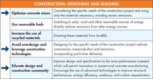
Design and construction professionals face significant challenges driven by increasing customer demands, rapidly changing material costs, strained supply chains, and the loss of workers going into trades. However, a more urgent issue is that climate change is a real and growing concern. Given that concrete is the most widely used manufactured material in the world, the Portland Cement Association (PCA) has challenged the design and construction industries to address the issue by developing a roadmap to carbon neutrality by 2050. Optimization, avoiding overdesign, designing for performance, and leveraging technology are critical parts of the path (Figure 1).
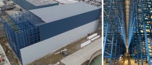
This article focuses on one opportunity to improve environmental outcomes and the competitiveness of concrete as a structural system by using advanced analysis, materials, and methods to design plain concrete in structural ground-supported slabs. Since structural ground-supported slabs are foundations that transmit vertical loads or lateral forces from other portions of a structure to the soil, the provisions of ACI 318, Building Code Requirements for Structural Concrete and Commentary, are applicable. These types of slabs are common in Automated Storage and Retrieval Systems (ASRS)with rack-supported roofs (Figure 2).
What is Plain Concrete?
The definition of plain concrete is structural concrete with no reinforcement or with less reinforcement than the minimum amount specified for reinforced concrete in the applicable building code.
Concrete strength in bending can be divided into two categories: a) Flexural Strength/Modulus of Rupture (MOR) – the stress that causes it to crack initially and, if it contains reinforcement, b) Residual Strength – the stress it can carry after a crack has developed.
Flexural Strength
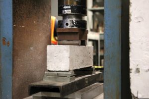
The flexural strength of concrete is generally inferred by the concrete’s compressive strength rather than being directly measured (ACI 318 and ACI 332, Residential Code Requirements for Structural Concrete). It can, however, be specified directly and measured with the three-point load test (ASTM C78, Concrete Beam Bend Testing) (Figure 3) or center point load test (ASTM C293, Standard Test Method for Flexural Strength of Concrete).
Increasing compressive strength typically increases flexural strength, but flexural strength can also be optimized by careful design of the concrete mix and special additives. For example, a concrete mix with large, angular, well-graded blended coarse aggregates provides higher flexural strength than a mix using small, round, gap-graded aggregates.
ACI 322-72, Building Code Requirements for Structural Plain Concrete, was the last code that allowed for direct design of plain concrete with flexural testing. Currently, allowable flexural strength is determined using a fixed multiplier 5√f´c of the compressive strength in the building code (ACI 318). In contrast, a higher multiplier, 7.5√f´c, is available in the residential code (ACI 332).
ACI 380, a new committee formed to pick up where ACI 322 left off in the 1970s, is investigating the feasibility of using a higher multiplier or a performance-based design based on the flexural strength for plain structural concrete. It would recommend modifying ACI 318-14 Equation 14.5.2.1a to use a higher multiplier of compressive strength or the actual specified flexural capacity (per ASTM C78) in place of the prescriptive 5√f´c for the allowable flexural strength of the concrete in ACI 318 as in Equation 1.
φMn = φfrSm (Eqn. 1)
where:
fr = MOR estimated taken as a multiplier √f´c or specified with required ASTM C78 testing
Mn = Nominal Moment Capacity
Sm = Section Modulus (bh2/6)
φ = Resistance factor for bending (0.6)
Residual Strength
Residual strength is the amount of force the concrete can take after a crack has formed. Plain concrete without any reinforcement has no residual strength. Steel rebar and wire mesh are the only forms of reinforcement recognized directly in ACI 318 for providing residual flexural capacity. While alternative reinforcement materials such as Fiber Reinforced Concrete (FRC) and Fiber Reinforced Plastic (FRP) rebar are proven in slab-on-ground applications, they are not currently recognized in ACI 318 as providing flexural reinforcement.
Design
Three methods for slab design are considered: elastic design hand calculation methods (Westergaard), yield line methods (Meyerhof), and linear finite element analysis.
Elastic Method
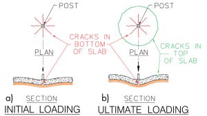
In the 1920s, Westergaard developed equations that provide the bending stress at the point of initial cracking in a slab-on-ground based on the loading and soil subgrade modulus (Figure 4a). The Westergaard approach is outlined in ACI 360, Guide to Design of Slabs-on-Ground, Chapter 7. This method typically leads to the most conservative design, given that it treats the initial cracking point at the bottom of the slab under the load as the ultimate condition.
Yield Line Methods
In the 1960s, Meyerhof developed a method of design that nearly doubled the efficiency of plain concrete pavement designs (Figure 4b).
The solution, which considers the redistribution of loads after initial cracks form on the bottom slab surface, was conceived originally for plain concrete pavements. The method has been adapted with lightly reinforced and fiber reinforced concrete. Walker and Holland, and ACI 360, suggest this design approach is a valid option for slab-on-ground design even with plain concrete.
Allowing stresses to redistribute reduces the required thicknesses by a factor of two or more. Resistance is computed using Equation 2, and closed-form equations for demand are published in several references such as ACI 360-10 Chapter 11.
Mn = (Mneg + Mpos) (Eqn. 2)
where:
Mn = Nominal Moment Capacity
Mneg = Flexural strength (MOR) measured using ASTM C78
Mpos = Residual strength from bottom reinforcement, zero for plain concrete
Testing has confirmed that even plain concrete ground-supported slabs have considerable capacity after the initial crack formation.
Finite Element Analysis
Finite element analysis (FEA) is a method permitted by ACI 318 Section 6.9 that is able to consider the exact load distribution accurately. In this method, the concrete slab-on-ground, post loads/reactions, and soil properties are incorporated into the computer model. SAFE, ADAPT, and RISAFoundation are commercially available software packages tailored to concrete foundation and slab-on-ground design.
For heavy post loads such as for ASRS shown in Figure 2, slab thickness is almost always controlled by the flexural strength of concrete. Worst-case bending moments for ACI 318 factored load combinations are obtained from computer models, and slab thickness is adjusted to keep bending stresses in the slab under allowable strength.
The Opportunity
Attaining the ambitious goal of carbon neutrality put forth by the PCA is feasible if the industry focuses on developing materials that fully utilize the design methods indicated above.
Available now:
- Design walls, footings, and structural slabs using linear elastic design with loads computed in accordance with ACI 318 Chapter 6 and resistance with ACI 318 Chapter 14 (5√f´c). This includes the use of finite element analysis in ACI 318 Section 6.9.
- In residential concrete designed in accordance with ACI 332, using flexural strength equal to 7.5√f´c is permitted. This extends the plain concrete allowable capacity in residential concrete by 50% over the 5√f´c currently allowed in ACI 318 Chapter 14.
The following should be considered:
- Revisions to ACI 318 Chapter 14 and ACI 332 Chapter 6 that allow a higher multiple of √f´c and/or actual modulus of rupture based on ASTM C78 for the design of plain structural concrete members.
- Revision to ACI 318 Chapter 14 and/or allowance in ACI 332 Chapter 6 that allow the use of moment redistribution methods for plain concrete ground-supported slabs, like that permitted for reinforced concrete foundations in ACI 318 13.2.6.2.
- Design considerations for steel reinforcement and/or alternative forms of reinforcement to provide post-crack capacity at the location of the first crack when the yield line method is employed.
In the meantime, ACI 318 Section 1.10 allows for alternative approaches. One example of an alternative approach is the use of the International Code Council Evaluation Service (ICC-ES) ESR 3949 for Helix 5-25 Micro-Rebar. This building product evaluation report contains a table of MOR values for concrete mixes derived from ASTM C78 testing. Design professionals may use these values as an alternative to those determined using the lower bound equation in ACI 318 Section 14.5.2 (5√f´c). The resulting higher nominal capacity available may be used to provide additional value in structural plain concrete applications such as slabs-on-ground, foundation walls, and footings by allowing for thinner sections and/or reducing the need for traditional reinforcement.
Examples
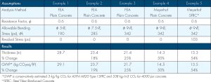
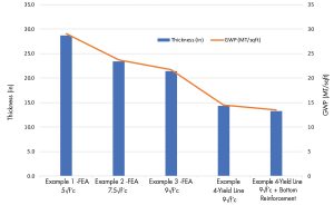
The design examples in the Table are based on the design of an ASRS slab with a rack-supported roof (Figure 2). Each example assumes the same loading configurations, concrete strength, and soil conditions. All designs include 50 lb/yd steel fiber. The steel fiber provides residual capacity in Example 5 and is used only for crack control in the other examples. Five approaches are considered with the required slab thickness and global warming potential (GWP) based on the ultimate limit state condition computed for each. The thickness and GWP are reduced as the assumptions change (Figure 5).
Conclusions
- Actual measured flexural strength and higher multipliers of √f´c have been successfully used to design structural ground-supported slabs. Reductions in thickness and global warming potential (kg CO2 generated by materials used) of about 25% are possible with this approach.
- Applying the yield line method to plain concrete allows a reduction in slab thicknesses and global warming potential by about 50%
- Applying the yield line method to concrete with bottom (positive moment) reinforcement (provided by steel reinforcement or alternative reinforcement such as FRC or FRP) allows for even thinner and lower carbon designs (more than 50% reduction).
- When allowed by code, alternative means and methods have been used successfully to satisfy code officials. Still, changes to the plain structural concrete chapter of ACI 318 would allow more widespread use of these field-proven methods.
Engineers who are already using methods like these need to communicate their experiences and support efforts (e.g., ACI 380) to revise codes. This can only help the industry answer the PCA challenge. Meeting this challenge will reduce the environmental impact of concrete designs and help engineers better serve clients with more durable and efficient structures.■
Acknowledgments: Thank you to Wayne Walker, P.E., S.E., FACI (SSI), for his comments and contribution of figures, and Justin Idalski, P.E. (MI) (Helix Steel), for his support of example calculations.
References
ACI Committee. Design of Slabs on Ground (ACI 360-10). American Concrete Institute. 2010.
Alani, Amir M., et al. “Structural behavior and deformation patterns in loaded plain concrete ground-supported slabs.” Structural Concrete 15.1 (2014): 81-93.
American Concrete Institute, ACI CODE-318-19: Building Code Requirements for Structural Concrete and Commentary, 2019, Michigan.
American Concrete Institute, ACI Concrete Terminology (CT-20), 2020, Michigan.
American Concrete Institute, Building Code Requirements for Structural Plain Concrete (ACI 322-72), ACI Committee 322, 1972, Michigan.
American Society for Testing and Materials, ASTM C78 “Standard Test Method for Flexural Strength of Concrete.” ASTM.
American Society for Testing and Materials, ASTM A820 “Standard Specification for Steel Fibers for Fiber-Reinforced Concrete.”
American Society for Testing and Materials, ASTM C293 “Standard Test Method for Flexural Strength of Concrete (Using Simple Beam With Center-Point Loading).”
Gates, Bill. How to avoid a climate disaster: the solutions we have and the breakthroughs we need. Knopf, 2021.
ICC-ES Committee, Helix 5-25 and Helix 5-25U Micro Rebar Reinforcements, ICC-ES, 2021 (https://icc-es.org/report-listing/esr-3949).
Meyerhof, G. G. “Load-carrying capacity of concrete pavements.” Journal of the Soil Mechanics and Foundations Division 88.3 (1962): 89-116.
PCA Roadmap to Carbon Neutrality. www.cement.org/docs/default-source/roadmap/pca-roadmap-to-carbon-neutrality_10_10_21_final.pdf.
Pinkerton, Luke R. “Structural Plain Concrete Gets a Fresh Look,” Concrete International, May 2021.
Roesler, Jeffery R., et al. “Fracture of plain and fiber-reinforced concrete slabs under monotonic loading.” Journal of Materials in Civil Engineering 16.5 (2004): 452-460.
Walker, Wayne, and Jerry Holland. “Design of Unreinforced Slabs on Ground Made Easy.” Concrete International 23.5 (2001): 37-42.