
Part 2
The American Society of Civil Engineers’ ASCE 7-22 load standard, Minimum Design Loads for Buildings and Other Structures, is now available, and substantive changes have been made to both the snow and rain provisions. This article is the second in a two-part series regarding these changes. Part 1 (STRUCTURE, January 2022) reviewed changes to the ground snow loads, which represents a shift away from uniform hazard to uniform risk, and the addition of a winter wind parameter to account for the variability in winter wind speeds on drift loads. This article reviews other revisions to the snow loads, including a more accurate estimation of the horizontal extent of windward drifts, revised thermal factors Ct to account for current trends in roof insulation and venting, and guidance on design loads for snow capture walls added to this edition. Also, changes were made to Chapter 8 to include a ponding head to the rain load, which provides a consistent approach to assess ponding.
Windward Drifts
The leeward roof step drift formation process is straightforward and reasonably well understood. Wind causes upper-level roof snow to be transported (i.e., blown) to the edge of the upper-level roof. A percentage of that snow transport (typically taken to be 50%) remains in the region of aerodynamic shade until the wind stops, the upwind snow source area is depleted, or the leeward drift becomes full. The situation for windward roof step drifts is more complex. Based upon measurements by Potac and Thiis in Norway, the initial trapping efficiency is nominally 100%. That is, all the transported snow initially stays upwind of the wall. If the windward drift grows large enough, wind streamlines along the snowdrift surface (snow ramp) move high enough up the wall to carry some windblown snow over the wall, dropping the windward trapping efficiency to less than 20%. The windward drift’s slope has a rise-to-run of 1:8 compared to 1:4 at the non-full leeward drift. For the same upwind fetch, ground snow load, and winter wind parameter, the cross-sectional area of the windward roof step drift could be larger or smaller than that for the leeward roof step drift. For roof steps with large differences in elevations, the windward drift’s trapping efficiency approaches 100%, producing a larger cross-sectional area than the leeward drift with its roughly 50% trapping efficiency. The reverse is true for small steps for which the net windward trapping efficiency can be closer to 20% (i.e., less than the 50% for leeward drifts).
For simplicity, the ASCE 7-22 Snow and Rain Load Subcommittee changed the windward drift rise-to-run to 1:8 but kept the windward drift height as 75% of the corresponding leeward drift height and kept the current right triangular shape for both. Hence, for the same conditions (i.e., same Pg, lu, and W2), the non-full leeward drift has a height of hd and width of 4hd, while the windward drift has a height of 0.75hd and width of 6hd (.75 x 8hd).
The advantage of these new provisions is a more accurate estimate of the horizontal extent of windward drifts. The disadvantage is in the determination of the governing drift at a step. Consider the typical case where the upwind fetch parameters for the leeward and windward drifts are different. Using the 7-16 provisions, one only needed to compare the windward and leeward drift heights to determine the governing drift since both had a rise-to-run of 1:4. Using the 7-22 provisions, one must determine the induced bending moments and shear forces in the individual structural components. It is possible that some structural components on the same roof would be governed by the leeward drift, while others would be governed by the windward drift.
Thermal Factor Ct
The thermal factor Ct in ASCE 7 is intended to account for the expected reduction in roof snow loads due to heat flow upward through the roof. There are, of course, other thermal effects, such as solar radiation and above freezing ambient temperatures. However, the other thermal effects result in a similar reduction in both roof and ground snow loads and hence do not influence the ground-to-roof conversion factor.
In ASCE 7-16, the Ct factors ranged from 0.85 for certain greenhouses to 1.3 for freezer buildings. For structures with human wintertime occupancy, the thermal factor is 1.1 for ventilated roofs and 1.0 for all others (unventilated roofs). Historically, these factors have generated minimal comment by practicing structural engineers.
However, starting in about 1995, ASHRAE and governmental authorities have been requiring (or recommending) increased levels of roof insulation. As a result, structural engineers involved in retrofit work started wondering if these insulation increases might result in more roof snow than envisioned by the old thermal factors, mainly based upon observations of structures with old levels of roof insulation.
The ASCE 7-22 provisions for Ct address these recent changes to roof insulation practice. Specifically, the current required insulation for modern ventilated roofs results in essentially no heat flow through the snow layer atop a ventilated roof “meeting the minimum requirements of the applicable energy code.” As such, in relation to the potential melting of roof snow, modern ventilated roofs act thermally the same as unheated roofs. Hence, the thermal factor for the modern ventilated roof is now Ct = 1.2.
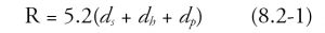
Similarly, increases in insulation levels for unventilated roofs resulted in revised Ct values in ASCE 7-22. In this case, the expected melting of roof snow due to heat flow upward through a simple thermal model was used. As described in more detail in O’Rourke and Russell, the model consisted of a snow layer atop an insulated roof layer. The critical parameter was the location of the 32° F isotherm. Melting of roof snow only occurs in below-freezing outdoor temperatures if the 32° F isotherm is at the bottom of the snow layer. If the 32° F isotherm is within the roof insulation layer, there is no melting of roof snow due to heat flow through the roof insulation/snow layers. Simulation using the simple roof thermal model with outdoor temperatures for several locations across the U.S. resulted in the Ct values for unventilated roofs shown in Table 1.
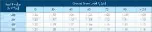
Notice, as one would expect, increasing roof insulation for any given ground snow load value results in less melting of roof snow and hence large Ct values. Also, note that Ct = 1.2 for ground snow loads of 15 pounds per square foot (psf) or less for all roof R-values. In such cases, the snow layer is so thin that the 32° F isotherm is always within the insulation layer; hence, there is no reduction in roof snow load due to heat flow up through the roof, the same as for an unheated structure.
Finally, note that the Ct values for a roof insulation value of R = 50 are close to or equal to 1.2, the unheated structure value. In these cases, the roof insulation layer is so thick that the 32° F isotherm is most often within the roof insulation layer.
Full Capture Walls
The addition of a new higher roof structure next to an existing lower roof structure leads to leeward snow drift loads atop the existing roof. These new drift loads were likely not considered in the original design of the existing low roof structure.
To avoid the often costly and challenging retrofit of the existing roof, structural engineers frequently envision a taller than usual parapet wall atop the new roof. The purpose of the new parapet wall would be to capture the expected drift snow atop the addition before it leaves the new addition, thereby eliminating the “unexpected” drift atop the existing roof.
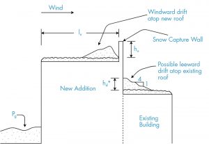
The ASCE 7-22 Commentary will provide guidance for both a full capture and a partial capture wall. By its nature, the captured drift atop the addition will be windward, as shown in the Figure. As mentioned above, the initial trapping efficiency at a windward drift is 100%. To achieve full capture, the parapet wall height above the new addition, ho, needs to be larger than 1.86 hd, where hd is the expected drift height for the leeward drift atop the existing roof for the case of no capture wall.
The ASCE 7-22 Commentary will also provide relations for the expected leeward drift height for a partial capture wall with ho < 1.86 hd. For a comparatively tall partial capture wall with 0.51 < ho/hd < 1.86, the expected drift height atop the existing roof hd* is
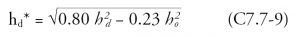
using the equation number in the ASCE 7-22 Commentary. For a comparatively small partial capture wall with ho/hd < 0.51
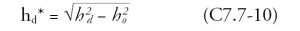
As one would expect, for ho = 0, equation C7.7-10 applies and yields hd* = hd. Also, note that at ho = 0.51 hd, both equations yield the same result of hd* = 0.86 hd.
Rain Loads
In ASCE 7-16 and previous editions, there is a requirement to perform a ponding analysis, yet there was limited guidance on performing that analysis. The commentary referenced the methods in Appendix 2 of the AISC Specification (AISC 360, Specification for Structural Steel Buildings). However, these provisions are of limited scope, and they are currently under ballot to be removed from the AISC Specification. A significant change to Chapter 8 of ASCE 7-22 applies a ponding head (dp) to the rain load, which provides a more consistent approach to assessing ponding. The new rain loads are based on the summation of the static head, ds, hydraulic head, dh, and ponding head, dp, using Eqn. 8.2-1, reproduced below.
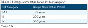
The static head is equal to the depth of water on the undeflected roof up to the inlet of the secondary drainage system for structural loading (SDSL). The hydraulic head is based on hydraulic test data or calculations assuming a flow rate corresponding to a rainfall intensity equal to or greater than the 15-minute duration storm with a return period and risk category given in Table 8.2-1. The ponding head is based on structural analysis using the depth of water due to deflections of the roof subjected to unfactored rain load and the unfactored dead load.
Other changes to Chapter 8 include adding a requirement that the inlet to the SDSL be vertically separated from the inlet to the primary drainage system by not less than 2 inches. This allows activation of the SDSL to serve as a warning that the primary drainage system is blocked or not working. Also, drainage systems for new construction are no longer allowed to discharge water onto existing roofs unless the existing roof is evaluated. Either the existing roof can support the loads determined by Chapter 8 or be upgraded to support the new rain loads.
Summary
This article is Part 2 of a two-part series summarizing some of the more substantive changes to the Snow and Rain provisions of ASCE 7-22. The changes to ASCE 7-22 include a more accurate estimation of the horizontal extent of windward drifts, revised thermal factors Ct to account for current roof insulation and venting trends, and guidance on the design loads for snow capture walls added to this edition. A significant change to Chapter 8 is the addition of a ponding head to the rain load, which provides a more consistent approach to assess ponding.■
References are included in the PDF version of the online article at STRUCTUREmag.org.
References
O’Rourke, M, Potac, J. and Thiis, T (2018). “Windward Snow Drift Loads,” Journal. Structural Engineering, ASCE, DOI: 10.1061/(ASCE) ST. 1943 -541X0002032, 04018033, 6 pages.
O’Rourke, Michael and Russell, Scott. Snow Thermal Factors for Structural Renovations. STRUCTURE, June 2019: 24-26.
AISC (2016). Specification for Structural Steel Buildings. ANSI/AISC 360-16.
Denavit, M. D. (2019). “Approximate ponding analysis by amplified first-order analysis,” Engineering Structures, 197, 109428.