
Secondary drainage system rain loads have been updated in the 2021 International Building Code® (IBC) to be consistent with ASCE 7-16, Minimum Design Loads and Associated Criteria for Buildings and Other Structures. The following text shows the specific change in the 2021 IBC. Strike-through indicates deleted text and underlined denotes new text.
1611.1 Design rain loads. Each portion of a roof shall be designed to sustain the load of rainwater that will accumulate on it if the primary drainage system for that portion is blocked plus the uniform load caused by water that rises above the inlet of the secondary drainage system at its design flow. as per the requirements of Chapter 8 of ASCE 7. The design rainfall shall be based on the 100-year hourly rainfall rate indicated in Figure 1611.1 15-minute duration event, or on other rainfall rates determined from approved local weather data. Alternatively, a design rainfall of twice the 100-year hourly rainfall rate indicated in Figures 1611.1(1) through 1611.1(5) shall be permitted.
R = 5.2(ds + dh) (IBC Equation 16-19)
where:
dh = Additional depth of water on the undeflected roof above the inlet of secondary drainage system at its design flow (in other words, the hydraulic head), in inches.
ds = Depth of water on the undeflected roof up to the inlet of secondary drainage system when the primary drainage system is blocked (in other words, the static head), in inches.
R = Rain load on the undeflected roof, in psf. Where the phrase “undeflected roof” is used, deflections from loads (including dead loads) shall not be considered when determining the amount of rain on the roof.
1611.2 Ponding instability. Susceptible bays of roofs shall be evaluated for ponding instability in accordance with Section 8.4 Chapters 7 and 8 of ASCE 7.

Change Significance
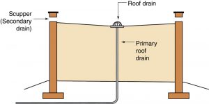
Secondary (overflow) system design (Figure 1) has been harmonized with roof rain load provisions for a structure to provide realistic expectations of the roof drainage system and potential roof loading by rainfall (Figure 2). The IBC is now consistent with ASCE 7 provisions. Calculations for the design mean recurrence interval and duration for determining the hydraulic head, dh, are available in both ASCE 7 and the IBC.

Legacy ASCE load standards’ design rainfall durations for plumbing systems were between 15- and 60-minutes for a 100-year mean recurrence interval. The 1995 Standard Plumbing Code used the 100-year/60-minute duration for primary drainage system design and a 100-year/15-minute duration storm for the secondary drainage system. In the 2018 IBC and International Plumbing Code (IPC), a 100-year/60-minute duration is used for both the primary and secondary systems. Note that using twice the 60-minute duration is close to the 15-minute duration rainfall rate for many regions. Also, note that 2021 IPC and 2021 IBC rainfall maps (Figures 1106.1 and 1611.1, respectively) both include a 60-minute duration rather than the 15-minute storm duration. However, the 2021 IBC, by giving two options – the 15-minute duration or twice the 60-minute duration – results in values similar to ASCE 7 when drainage pipe or scupper flow rates are calculated. Note that the 2021 International Plumbing Code has not yet been updated to reflect the 100-year/15-minute (or twice the 100-year hourly) duration rainfall event design requirement for secondary drainage systems; the structural engineer would be advised to coordinate with the plumbing engineer to ensure that the secondary drainage systems are designed for the higher rainfall rate.
The best source for rainfall data is the National Oceanic and Atmospheric Administration (NOAA) National Weather Service Precipitation Frequency Data Server – Hydrometeorological Design Studies Center (hdsc.nws.noaa.gov/hdsc/pfds/index.html) for precipitation intensity (inches per hour) based on the 100-year mean recurrence interval. NOAA’s data lists both 15-minute and 60-minute duration data.
Details of Load and Drain Size Calculations
To understand why this makes a difference, the following examples show how to determine rain load, R, assuming rainfall for the city of Cedar Rapids, Iowa. The first example uses 2018 IBC requirements, and the second uses 2021 IBC requirements.
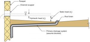
Secondary drain size and geometry affect the structural engineer’s determination of a maximum height of water above the roof surface using variables ds and dh for static and hydraulic head (Figure 3). Secondary drains should be specified, if possible, to keep rain loads reasonable. Engineers should be aware of different secondary drain options available to plumbers and clearly communicate how changes, especially to secondary drain geometry, can impact design rain loads on a building. Important parameters to communicate include assumed static head, hydraulic head associated with secondary drain or scupper size and geometry, rain load, and rainfall rate.
2018 IBC Design Example:
60-minute rainfall total for primary and secondary systems.
Design rainfall: 3.30 inches for 100-year mean recurrence, Cedar Rapids Station No. 1.
Calculate primary and secondary drain size and the resulting rain load, R.
Primary Drain
Depth of water (in 1 hr): 3.30 inches (NOAA)
Tributary area (primary drain): 100-ft by 50-ft = 5,000 ft2
Flow rate (volume) to maintain roof drainage:
Q = 0.0104 × A × i (ASCE 7-16 Equation C8.3-1*)
where:
Q – flow rate to maintain drainage rate equal to rainfall rate
A – tributary area
i – water depth in inches per hour
* The 0.0104 factor in the equation converts area, in square feet, and rainfall rate, in inches per hour, to gallons per minute.
A = 50 ft × 100 ft = 5,000 ft2
i = 3.30 inches/hr
Q = 0.0104 × 5,000 ft2 × 3.30 inches/hr = 172 gal/min
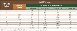
From Table 1, the minimum drain size is a 4-inch vertical pipe or 6-inch horizontal drain with a minimum slope of 1⁄16-inch per foot.
Secondary Drain and Rain Load (R) Calculation
Given:
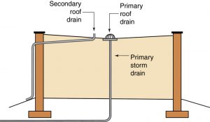
ds = specified distance from the roof surface to the bottom of scupper (Figure 4) or top of secondary drain pipe (Figure 5)
dh = calculated (tabulated) height of water above the base of scupper or secondary drain based on drain geometry
Flow rate (volume) to maintain roof drainage through a scupper or secondary drain is calculated for the secondary drain since the primary drain is assumed to be completely blocked. The secondary system’s design rainfall is 3.30 inches per hour per the 2018 IBC. The flow rate, Q, will be 172 gal/min, identical to the primary drain system. This rain load must leave the roof at the same rate it is falling or faster.
Typically, once the structural engineer determines the rainfall, static head, hydraulic head, and rain load on a roof, a plumber can size the secondary system pipes or scuppers to a flow rate of 172 gal/min or greater. An engineer does this check as an iterative process to keep rain loads on the roof rational by limiting the hydraulic head to a reasonable value. Engineers should be aware of different secondary drain options available to plumbers and clearly communicate how changes, especially to secondary drain geometry, can impact design rain loads on a building.
To calculate R:
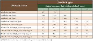
dh (hydraulic head) = 5 inches for a 6-inch-wide, 6-inch-high, closed-top scupper which corresponds to a flow rate of 194 gpm (Table 2) which is sufficient for the calculated flow rate of 172 gpm.
ds (static head) = 6 inches (specified distance from the roof surface to the bottom of the scupper)
R = 5.2(ds + dh) = 5.2(6 in. + 5 in.) = 57.2 psf (IBC Eq 16-19)
As a second iteration, a 24-inch-wide scupper (open- or closed-top of any height) handles 200 gpm with a corresponding 2-inch hydraulic head. This would reduce the rain load to a more reasonable 41.6 psf.
Note: The 5.2 value in the equation converts depth of water, which is in inches, to pressure in pounds/square foot (psf) using the density of water of 62.5 pounds per cubic foot (pcf) and the conversion inches to feet (12 inches per foot); therefore, (62.5pcf)/(12in./ft) = 5.2 psf per inch of water depth.
2021 IBC Design Example:
60-minute rainfall duration for the primary system, 15-minute rainfall duration for the secondary system.
Design rainfall for Cedar Rapids Station No. 1:
3.30 inches for 100-year mean recurrence (60-minute)
1.72 inches for 100-year mean recurrence (15-minute)
Calculate primary and secondary drain size and resulting rain load, R.
Primary Drain
Using the parameters from the 2018 IBC Example, calculation of the primary drain diameter per Table 1 requires a minimum 4-inch vertical pipe or 6-inch horizontal drain (minimum slope of 1⁄16-inch per foot).
Secondary Drain and Rain Load (R) Calculation
Flow rate (volume) to maintain roof drainage through scupper or secondary drain is the flow rate calculated for the secondary drain. The primary drain is assumed to be completely blocked.
Flow rate (volume) to maintain roof drainage rate equal to rainfall rate:
Q = 0.0104 × A × i (ASCE 7-16 Equation C8.3-1)
where:
Q – flow rate to maintain drainage rate equal to rainfall rate
A – tributary area
i – water depth in inches per hour (must convert 15 min interval to equivalent hour interval)
A = 50 ft × 100 ft = 5,000 ft2
i = 1.72 inches/ 15 minutes × 60 minutes/ hour = 6.88 inches/hr
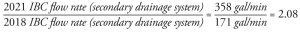
Q = 0.0104 (5,000 ft2) (6.88 inches/hr) = 358 gal/min
Note that a 15-minute design rainfall has approximately 2 times the flow rate of the 2018 IBC 60-minute design rainfall. This is true for much of the United States but check each location to make sure it is true in that region rather than assuming a fixed 100-percent increase in flow rate.
To calculate R:
dh (hydraulic head) = 3 inches for a 24-inch-wide, open- or closed-top scupper corresponding to a flow rate of 360 gpm (Table 2), sufficient for the calculated flow rate of 358 gpm.
ds (static head) = 6 inches (specified distance from the roof surface to the bottom of the scupper)
R = 5.2(ds + dh) = 5.2(6 in. + 3 in.) = 46.8 psf (IBC Eq 16-19)
Secondary drain size impacts flow rate but drain size and geometry impact hydraulic head levels. Therefore, to keep the rain load to reasonable design levels, larger secondary drains and geometries should be explored to minimize hydraulic head levels. The examples show that flow rates in the 2021 IBC are approximately double for secondary drain design. However, for comparably sized roofs and secondary drains (24-inch scuppers), the difference in the hydraulic head is 1 inch, which only increases the rain load by about 5 psf.
Conclusion
Secondary drainage system rain loads have been updated in the 2021 IBC to be consistent with ASCE 7-16. For plumbers to be aware of the change to a 15-minute per 100-year rainfall duration, engineers should clearly communicate how changes, especially to secondary drain geometry, can impact design rain loads on a roof.■