
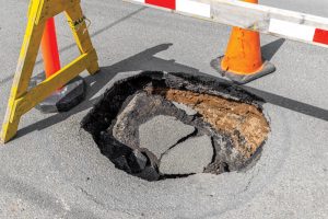
Rapid transportation by metro has become an indispensable development for many modern cities. Due to the depth and length of the tunnels, these urban subway lines are often built using circular tunnel boring machines (TBM). Two common types of TBMs are slurry TBMs and earth pressure balance (EPB) TBMs. While the tunnel shield and completed segmental tunnel linings (usually discrete precast concrete panels assembled together or precast rings) are relatively safe, the TBM excavation process can be potentially dangerous. This article looks at some measures and good practices to avoid sinkholes (Figure 1) during closed-face tunneling. The intricacies of tunneling and TBMs are much broader than the overviews included here.
Key Principles of TBM Construction
A TBM typically consists of a cutterhead, excavation chamber, and a shield in very simplistic terms. The strong cylindrical steel shield provides a safe environment for removing spoils from the excavation chamber and erecting the permanent linings. At the front of the TBM, a cutterhead is equipped and configured strategically with disc cutters to break down rock and appropriately sized openings to allow excavated materials to be removed from the face. Face pressure is regulated via slurry flow and plastic paste discharge for slurry and EPB TBMs, respectively. It is important to note that the cutterhead needs to overcut a slightly larger diameter to allow the shield to advance by jacking against completed linings. Similarly, the linings being erected within the shield means that there is a “tail-void” or annulus which needs to be grouted to minimize risks of ground and lining movement.
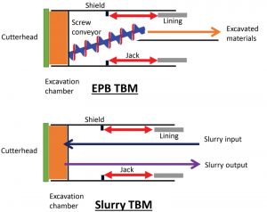
EPB TBMs are more suited for cohesive soils (clay/soft ground), while slurry TBMs are for cohesionless soils (sand/rock/mixed ground of soil and rock) with additives/conditioning agents and bentonite slurry added, respectively, to condition the excavated spoils for easy removal. Slurry TBMs are more elaborate in setup as the slurry needs to be recycled, requiring a separation plant on the ground. The better control of face pressure for slurry TBMs allows such TBMs to be used in more difficult (e.g., high groundwater and permeable) and heterogeneous ground conditions. Slurry TBMs are also sometimes equipped with powerful crushers and grizzly bars to deal with boulders (or rock debris) and prevent jamming the TBM. Choosing the correct TBM type with adequate and suitable specifications to deal with the site-specific ground conditions is a critical first step in ensuring safe tunneling (Figure 2).
Ground Settlement
A sinkhole is a case of a sudden (and usually substantial) void formed at the ground surface. The usual small magnitude ground surface settlement caused by TBM tunneling can be estimated using a Gaussian (normal) distribution curve. This settlement is due to the volume loss in the ground in the process of tunneling. Volume loss can include losses at the TBM face, the shield, and the tail void. The Gaussian distribution assumes that the area encompassed by the curve is equal to the volume loss. Two key parameters are required to define the curve: the volume loss, Vl, and i, the distance from the tunnel centerline to the inflection point. The volume loss is usually expressed as a percentage of the tunnel face area, say 0.5% to 3%. i is a fraction of the tunnel depth, which can typically be 0.25H for sand and 0.5H for clay, where H is the depth to the tunnel centerline. For clay, this value can range from 0.4H to 0.7H for stiff clay and soft clay, respectively. Although obvious, to minimize impact to property and structures, surface settlement needs to be minimized, and therefore, volume loss needs to be as small as possible, preferably below 0.5%.
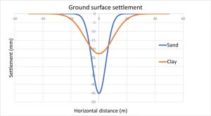
Figure 3 shows a comparison of ground surface settlement for TBM in clay and sand. The tunnel diameter is 19.7 feet (6m) and located at 65.6 feet (20m) below ground, using a volume loss of 2%. Ground settlement in stiff clay and sand will show a narrower trough width. Therefore, the maximum settlement would be higher than soft clay to maintain the same area enclosed by the curve, assuming the same volume loss.
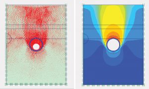
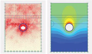
A simplified finite element simulation of volume loss in sand and clay using volume contraction is shown in Figures 4 and 5. It can be seen that the settlement trough in sand is very narrow, with much settlement occurring on top of the tunnel and the soil movement wedge surface propagating upwards at an angle of 60° (measured from horizontal) to almost vertically (like a chimney-type mechanism). In clay, the settlement trough is much wider, and some designers assume the soil movement wedge to be at 45° measured from the horizontal tunnel centerline (springline). This is due to the plastic flow of soft clay, where there is substantial movement horizontally from the sides of the tunnel due to the generally higher horizontal stress compared to sand. Whereas for sand, the frictional nature of the material means that vertical stress is usually higher than horizontal stress, resulting in a greater tendency of downward soil displacement above the tunnel. In addition, the failure surface of sand tends to propagate upwards in a path of least resistance, which is vertically upwards because the frictional strength decreases most rapidly in the vertical direction with decreasing confining stress.
TBM Face Stability
The tunneling process is an unloading process as soil support is removed when the ground is excavated. Therefore, the control of face pressure during TBM operation is critical. Inadequate face pressure could result in the face lacking support and the soil becoming unstable, causing ground loss and possibly a sinkhole. Conversely, the soil might be forced upwards if the face pressure is excessive, causing a blow-out or ground heave. Slurry might also be leaked out.
During TBM excavation, the TBM face has to balance two primary sources of loadings, namely from soil and water. In terms of total stress for undrained loading, where water is not considered explicitly, the face pressure required to prevent collapse can be calculated from overburden pressure less Nccu, where Nc is the stability number (equal to 9 for deep tunnels with soil cover greater than 3 times the tunnel diameter), and cu is the soil undrained shear strength. Notice that Nccu is analogous to the ultimate bearing capacity of 9cu in piles. Surcharge (if extensive in area) and pressure variation, typically 1.45 to 4.35 psi (0.1 bar to 0.3 bar or 10 to 30 kPa), can be included if necessary. To control settlement, a more stringent Nc is used. For example, to control settlement below 2%, Nc could be 4.5 (half of 9).
Similarly, for effective stress, the face pressure required to prevent collapse can be calculated from the sum of water pressure and effective soil balance pressure (submerged soil unit weight times tunnel diameter) less soil cohesion, with some coefficients applied (e.g., 0.2 and 2 respectively for effective soil balance pressure and soil cohesion). The water pressure term is going to be the dominant factor when the groundwater table is high. Again, to control settlement, a higher pressure is necessary to balance the soil pressure (use a higher coefficient, e.g., 0.6). The maximum face pressure should not be greater than the total vertical overburden pressure to prevent ground heave.
Occasionally, operatives may need to enter the excavation chamber to inspect, repair, clear obstructions, or change worn-out tools (also known as cutterhead interventions). In such an instance, compressed air is required to balance the water pressure to prevent water ingress. As soil pressure cannot be balanced, it may be necessary to ensure such stoppage and interventions are carried out in stable ground, for example, docking within a jet grout block. In addition, dewatering and grouting might be required. Ensuring that the membrane filter cake (an impermeable layer on the soil surface formed by small particles clogged or wedged together under pressure) is maintained and effective is crucial for compressed air support, especially during prolonged stoppages.
Controlling Over-Excavation
Another critical aspect in preventing sinkholes is in the control of over-excavation during TBM tunneling. The theoretical volume of soil to be taken out can be determined by the tunnel geometry, i.e., the product of the face area and length of the tunnel. If the actual excavated amount exceeds this theoretical amount, it means there is over-excavation. Over-excavation can be potentially dangerous because when more soil is taken out from the ground, underground voids are formed, and these could culminate in a sinkhole being formed at the ground surface. In addition, the formation of a sinkhole can be sudden with few tell-tale signs. Therefore, closely monitoring over-excavation and setting an over-excavation limit is crucial in preventing sinkholes.
Determining over-excavation is not a straightforward task because the soil volume in situ is obviously different from the volume of loose soil after excavation. Some designers estimate the expanded volume or swell of the soil after excavation by applying a “bulking factor” of 1.2 to 1.3 for soil and even higher for rock. However, additives or slurry are added for closed-face tunneling, either EPB or slurry, and need to be accounted for. Furthermore, there is a possibility of water intrusion and additive or slurry loss into the ground. Ground make-up is also likely to vary along the TBM alignment. Therefore, designers have to be aware of the limitations and significance of over-excavation monitoring.
While soil volume may be different before and after excavation, the weight or mass of soil must remain the same. For a slurry TBM, the measurement of flow and fluid density at the input and output is used to monitor over-excavation. As an illustration, to find out the volume of soil excavated, the mass excavated can be found by first multiplying density with flow and time and taking the difference at the input and output pipes. Then, volume can be estimated by dividing mass by density. EPB measurement methods include physical muck skip counts and direct weight measurements.
Designers for TBM tunneling should always specify the limit of over-excavation allowed. Typically, this can be a value of 15% to 20% deviation in volume excavated for a single ring or a rolling average of 5 to 10 rings. When such a limit is breached, the tunneling team needs to know what immediate actions are required for reporting, verification, review, and remedial work. The response required might vary according to the risk to the public; for example, depending on whether tunneling is over a greenfield site (minor consequence) or in close proximity to existing buildings or critical infrastructures (severe consequence). When the over-excavation limit is breached, it is essential not to excavate further until verification and review are done to confirm that it is safe.
High-Risk Activities
Designers need to be aware of several high-risk activities during TBM tunneling. These include break-in/break-out from shafts, stoppage and interventions, mixed ground (soil and rock) conditions, worn-out cutting tools, and TBM flushing for a slurry TBM. Flushing is a process to circulate slurry in an attempt to revive a choked or jammed TBM. Without shield advancement, the slurry discharge could easily result in over-excavation. Therefore, such a procedure must only be carried out under authorization and close supervision with adequate control and precautionary measures in place. The tunneling team must follow strict procedures when encountering unexpected events, such as a jammed TBM. This is to avoid allowing the TBM operator free rein in carrying out repeated and extended flushing and discharging excessive materials. It is always tempting to repeatedly run the slurry flow in the excavation chamber to revive a jammed TBM.
A mixed-face condition occurs where the TBM face has both soil and rock. This is particularly challenging for TBM because of the vastly different stiffness of soil and rock. As the rock at the bottom of the TBM face resists the cutterhead’s advance, the soil at the top of the TBM is continuously drawn into the excavation chamber. Therefore, over-excavation can quickly occur. In addition, broken rock fragments that are too large to enter the cutterhead openings are trapped in front of the TBM and rotated. This overbreak also contributes to over-excavation due to the drawing in of more material compared to TBM advancement.
Precautionary and Remedial Measures
In built-up areas, it may be helpful to visually annotate the TBM alignment on the ground surface. In addition, surface surveillance by eye helps detect visible ground settlement, especially when ground settlement readings are not yet taken or made available. In critical areas, it is also helpful to have a drilling rig ready and on standby so that any backfilling of voids by grouting can be carried out immediately.
Ground improvement by grouting is a commonly employed technique in TBM operations. In difficult ground conditions such as mixed-face tunneling, grouting the weaker zones helps to provide a more stable excavation process and minimize the risk of over-excavation. Grouting may also be used in other higher-risk areas, such as break-in/break-out locations.
Conclusion
The avoidance of sinkholes is a crucial aspect of safe TBM construction. Starting with a good understanding of the ground conditions, a suitable TBM tunneling method and machine with appropriate capabilities can be selected. Maintaining adequate face pressure and working within allowable over-excavation limits are the two main control measures preventing sinkholes. When over-excavation occurs, a common error is to rely on grouting a sinkhole as an afterthought in an attempt to rush through tunneling with no regard for over-excavation and excessive slurry discharge. The better way is to suspend excavation and restart after verification and review to confirm it is safe to continue.■