
Part 3: Structural Investigations
This four-part series discusses the adaptive reuse of the Witherspoon Building in Philadelphia, Pennsylvania (Part 1, STRUCTURE, September 2021, Part 2, October 2021). Part 3 continues the discussion of the structural investigations – specifically the main roof and original mechanical penthouse – conducted to understand the existing structure better. Numbered photos are provided in the print version of the articles; lettered photos are provided only within the online versions of the articles.
Structural Investigations (continued)
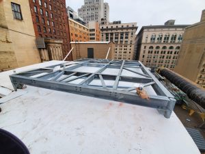
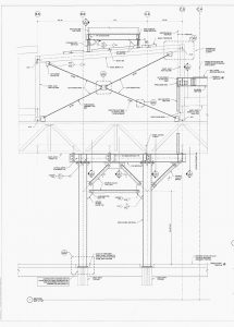
Results of the main roof and original mechanical penthouse investigation indicated that the high penthouse roof had sufficient reserve load-carrying capacity to support proposed new mechanical rooftop units (RTUs) that serve the residential units. However, it was necessary to design steel beam support dunnage that clear spanned between the penthouse columns to prevent imposing any load directly on the book tiles and bulb tees (Figure K). The increased lateral load on the penthouse due to the raised RTUs also required additional vertical X-bracing (Figure 11) to be installed inside the penthouse between the existing cast-iron columns and below the high roof beams. In addition, the installation of the X-brace connections was designed to avoid welding to the cast-iron columns by only connecting to the existing beams.
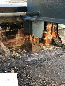
During the project’s construction phase, direct tension testing of the penthouse X-brace rods was conducted. This was to ensure correct rod pre-tensioning via turnbuckle rotation was performed without yielding the ½-inch-diameter rods. In addition, during the high roof dunnage construction, it was necessary to remove some of the brick masonry façade wall at the northeast corner of the passenger elevator machine room penthouse to access the existing column so that it could support the southwest corner of the dunnage. After removal of the brick, it was discovered that the steel wide flange column that supported the penthouse roof had been spliced on top of an existing Gray column (Figure 12).
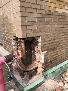
In addition, corrosion of both the wide flange column and Gray column had occurred due to moisture infiltration from a failed penthouse parapet coping above. The damage was corrected by cleaning the steel of all corrosion by-products to determine the extent of section loss, adding welded headed studs to the column sections, then encasing the members in a reinforced concrete pilaster that recreated the masonry corner of the penthouse. Encasing the steel columns in concrete strengthened them to offset the loss of section and protected the steel from further corrosion.
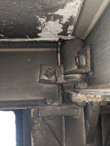
As a part of the investigation, it was also discovered that a few of the mechanical penthouse cast-iron columns were cracked at the beam web connection clip extensions that had been cast with the original pipe section (Figure 13). The source of the cracking was unclear; however, it was assumed that the cracks occurred during the original handling and erection of the columns due to the brittle nature of cast iron. It also appeared that the clips were intended for lateral support of the beams during erection only and served no actual structural function in the as-built condition. Nevertheless, new bracing angles were added between the affected beams and adjacent orthogonally framed beams at the same column.
Investigation results also made it necessary to design and detail the exterior assembly space as steel dunnage framing that spanned between the existing main building columns. However, reinforcing the lateral resisting system between the main roof and 11th floor was unnecessary because the increase in horizontal forces was determined to be less than 10% of the existing lateral loads at the roof level, as allowed by the International Existing Building Code (IEBC).
To avoid imposing assembly space dunnage loads on the existing clear span roof trusses, it was necessary to extend new columns up from the top of the 11th-floor main building columns to create rigid frames that in turn provided a platform for additional columns, which straddled each side of a truss and supported the new rooftop dunnage framing (Figure L). Also, a subsequent additional investigation was completed at the main roof, 11th floor, and ceiling framing impacted by the proposed new elevator and stair penthouses, which confirmed the original roof investigation conclusions. Unfortunately, the design associated with all of the above, except for the RTU dunnage, was excluded from the project due to the high cost of the proposed renovations.
Mechanical Penthouse and Cooling Tower Dunnage
Both the existing mechanical penthouse and cooling tower dunnage had been constructed well after the original building existed. The purpose of their structural investigations was to determine the ability of the same two structures to support the proposed new mechanical equipment and chillers, respectively. The investigation was required because there were no existing drawings available for either structure. Investigation findings are provided below and were based on steel coupon test results of a typical penthouse floor beam and roof joist of approximately 40 ksi and 50 ksi, respectively.
Cooling Tower Dunnage
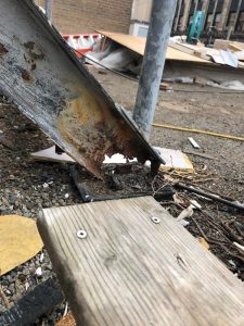
Investigation results of the existing cooling tower steel dunnage for the proposed new chillers indicated that, in general, the existing exposed framing could support the new equipment once the existing cooling towers were removed and the existing steel was cleaned and repainted to prevent further corrosion. However, unsafe structural conditions were observed at the two easternmost column post supports, immediately adjacent to the building’s edge, due to excessive steel corrosion and almost complete section loss (Figure 14).
The building owner was immediately notified of the unsafe conditions; however, the conditions were not corrected until much later in the project when similar corrosion was observed at all other dunnage column supports. In the interim, the existing cooling tower equipment was removed from the dunnage. Damaged columns were either replaced with new steel HSS columns or, if the corrosion was not too severe, encased in a reinforced concrete plinth that included headed studs welded to the original steel column.
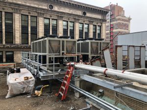
After the equipment was removed, the steel dunnage was cleaned and assessed. This resulted in the discovery that section loss due to corrosion exceeded 5% of the original area; therefore, it was necessary to weld reinforcing plates to the wide flange members to offset cross-sectional area loss. It was also necessary to design new steel grillage framing on top of the existing dunnage to marry the new chiller equipment to the existing framing footprint. New open steel grating catwalks were also provided, along with new support framing for the chiller piping between the existing dunnage and mechanical penthouse as required to avoid placing excessive pipe loads on the main roof framing below. The completed chiller dunnage and pipe support framing is shown in Figure M.
Mechanical Penthouse
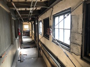
In general, the condition of the existing penthouse structure was fair; however, isolated cracking of the perimeter concrete base wall and moderate corrosion of the interior floor and roof framing were observed. Further, severe corrosion at the exterior steel stair stringers (Figure N) between the penthouse and main roof, which had resulted in complete loss of section in some areas, required that the damaged area of the stringer be demolished and replaced. In addition, isolated spalling of the floor slab soffit was also observed.
Although the existing 6-inch concrete floor slab capacity could not be accurately determined due to a lack of information concerning internal reinforcing, it was confirmed that the existing steel floor beams had a superimposed, service uniform load-carrying capacity of 100 psf. The open web steel roof joists were determined to have a load-carrying capacity of 16 psf in addition to all existing dead loads associated with the roof structure, roofing, and minimum roof live load of 20 psf.
The available capacity of the existing floor was considerably less than that imposed by the new mechanical equipment. As a result, it was necessary to design an independent, steel beam dunnage frame erected immediately above the existing penthouse floor slab to support the new equipment. The new framing clear-spanned between existing perimeter penthouse columns, which could support the new loads, including the existing main building columns below. It was also determined that the existing roof framing had adequate capacity to support the suspended mechanical piping associated with the new penthouse equipment.
Freight Elevator
Machine Room Penthouse
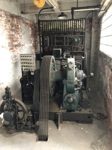
The existing freight elevator penthouse floor framing consisted of three 15-inch-deep steel wide flange blocking beams that directly supported the elevator machine loads. The blocking beams were supported by W14 machine beams that were in turn supported by W16 beams that spanned east and west between W24 girders. The W24 girders were supported by two perimeter building columns at the north exterior side of the penthouse. One framed into the northernmost roof truss at the south end of the W24 girders, while the other framed into an interior main building column. The penthouse floor, also supported by the beams described above, consisted of a solid concrete slab. The floor beam framing also supported a perimeter, multi-wythe brick façade wall, a steel-framed roof, a solid concrete roof slab, and the elevator hoist beams. The existing Otis elevator machinery before its removal is shown in Figure O.
Penthouse framing analysis included determining the impact of the new loading, provided by the elevator manufacturer, on the moment and shear capacity of the existing framing described above. In addition, the deflection of the framing members was assessed based on the criteria of American Society of Mechanical Engineers A17.1 (ASME A17.1). Analysis results, which were based on a steel coupon test from an existing penthouse roof hoist beam that revealed a yield strength of approximately 47 ksi, indicated that the moment and shear capacities of the 15-inch blocking beams, W14s, W16s, and W24 girders were adequate to support the proposed new elevator loads. As a result, it was also assumed that the existing beam end connections were likewise adequate for the new loading.
Based on ASME A17.1 Section 2.9.5, allowable deflections of elevator equipment support beams must be less than span/1666. While the calculated deflections of the blocking beams and W14 beams were less than this same amount due to the proposed new equipment, deflection of the W16 beams and W24 girders would be more than the same allowable deflection and were therefore not capable of safely supporting the proposed new loads. As a result, structural reinforcing was developed for the W16s and W24s.
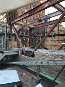
Strengthening the W16 and W24 beams involved installing vertical steel members diagonally between the floor beams and the roof beams above to create story-high trusses (Figure 15). In addition, due to the increase in the minimum-code roof snow load requirements since the existing Otis elevator was installed, the roof truss that supported the W24 penthouse floor girder had to be re-supported with an additional column between the top of an interior 11th floor column and the bottom chord of the existing truss to reduce the span.
Shaft Vertical Rail Supports
This investigation did not include an analysis of the existing vertical cab guide rails or counterweight system because they were considered part of the operating equipment for which the elevator manufacturer was responsible. Unlike the vertical cab guide rails, it was also determined that the counterweight system did not impose any additional load on the existing structural supports located within the shaft. Therefore, neither the vertical guide rails nor the counterweight system was included in the investigation and analysis of the existing internal shaft support framing and related floor framing supports.
The primary deficiency documented in the shaft as a result of the investigation was the existing connections between the vertical guide rails and the existing horizontal support members at each floor level. Further, it was determined that the existing horizontal support beams, spanning north and south at the east and west guide rails, were also not capable of supporting the new imposed loads. As a result, new rail support beams were designed and installed with the existing supports abandoned in place. However, the related floor support beams located around the perimeter of the shaft could support the new loads. The elevator manufacturer also provided new clamping bolt connections between the existing rails and the new supports and installed a properly-sized bearing plate at the base of the rails on top of the existing concrete pit slab.
Part 4 of this series continues the structural investigation discussion, including column capacities and connections, new floor openings, and other renovation-related issues.■