
Applying Computational Design Logic to the Quality Control Process
The future of structural engineering is inextricably linked with computational design. Algorithms and data will be the basis upon which the industry develops. That is not to say that engineering judgment and expertise will be replaced by artificial intelligence. Instead, the possibilities of computer programming will continue to enhance the capabilities of structural engineers just as the widespread adoption of the computer did in the 1980s. Some engineers in the industry have been working in the field of computational design for over a decade. Others have been slower to adapt.
Whenever the entry point, engineers will find they can apply the underlying skills and thought processes required for computational design to a far wider range of tasks than expected. It is a common misconception that the methodology is best utilized on high-profile and/or complex projects. While that is an important application, it is not relevant to most of the industry. Most structural engineers can, however, benefit from implementing computation design principles, specifically when utilized within quality control processes.
Computational design has been well documented as a tool used to rapidly develop design alternatives within a defined solution space. Using this methodology, an engineer can find an optimal solution for a given problem by iterating through different combinations of variables. Genetic algorithms ease this process by automatically filtering out the undesirable outcomes, as defined by the user. These algorithms focus on core parameters like volume, cost, performance, etc., and are extraordinarily useful during the schematic design phase, when design options are still rapidly changing. Rather than making the generalized assumptions that were once required to maintain aggressive project schedules, structural engineers now have access to timely, meaningful data that can be used to make significant project decisions during schematic design. Though often viewed as the final deliverable of computational design efforts, schematic design studies should not be the point when the process is abandoned for traditional workflows.
At its essence, computational design is a data management process that can be applied to every facet of a project. It has recently become widely adopted, in part due to the development of visual programming tools such as Grasshopper® for use with Rhinoceros®, and Dynamo® for use with Revit®. Users no longer need to be fluent in a specific programming language to create powerful computer scripts. Using preprogrammed components and a linear logic-based approach, engineers with average computer proficiency can develop scripts to make their workday more efficient. More specifically, engineers can develop scripts that provide quality control checks to ensure that design data (load diagrams, framing layout, beam reactions, column forces, etc.) is accurately considered and documented throughout the duration of projects.
Structural engineers use a multitude of different analysis programs published by competing software developers. Designs are then documented in yet another program to create the drawings upon which contractors base their own plans, which are ultimately used for construction. It is a complicated process that traditionally has relied upon human review to catch errors in data transfer. However, tools such as Grasshopper and Dynamo provide an opportunity to supplement human review with custom-developed scripts that compare the data at each step of the process. This ensures that nothing is outdated, lost, or unintentionally altered. Engineers are thus able to repeatedly check everything from architectural coordination items to the strength of critical connections without devoting company resources away from other tasks.
Architectural Coordination
The modern project workflow encourages architectural updates throughout the duration of a project. For better or worse, changes are often made within the architectural drawings without the structural engineer being notified. Revit users may receive a coordination review notification, but this process is incredibly time-consuming due to the vast number of changes. By combining engineering judgment with data extracted from the design documents, however, an engineer does not need to review each minute adjustment.
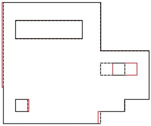
Consider, for example, slab edge adjustments. A computer script written within Grasshopper and/or Dynamo can isolate the floor slabs and extract their perimeter curves. That data can then be used to recreate the slab edge within Rhino3D. Corresponding data would be extracted from the analysis program used to design the slab and then imported into the same Rhino3D file. The two slabs are compared and subsequently highlighted wherever deviation exceeds a user-specified tolerance using preprogrammed Grasshopper components. An engineer can then focus on the portions of the slab that have significantly changed and update the analysis model accordingly. If greater automation is desired, updating the slab edge within the analysis model may also be written into the script.
A similar approach can be applied to coordinating architectural plans and loading in the structural analysis model. Using Grasshopper and its data manipulation capabilities, engineers can extract floor loading data from analysis models, filter the loads based on type and magnitude, and then overlay that information on architectural plans. With the relevant information in a single view, it is easier for an engineer to verify that the loads in an analysis model are coordinated with the architectural plans. More advanced computational designers may take this further by programming the script to extract the room and/or floor finish data from Revit, associate that information with structural loading from a standardized database, and ultimately compare it to the loading over that same area in the analysis model.
Structural Coordination
Coordination and quality control within the inner-office workflow is critical for safe and efficient project delivery. One of the most critical steps in these processes is ensuring data from analytical models is accurately conveyed on design documents. This includes everything from structural framing layouts to connection reactions. Engineers proficient in computational design methodology can write computer scripts to automate many of these tasks in Grasshopper and/or Dynamo.
Major structural analysis programs can export model information in various data formats that Grasshopper and/or Dynamo understand. Exporting data is often straightforward, but it must be done logically and in a well-documented, repeatable manner. This point is emphasized because even a small change in exported data formatting can cause issues with the best-written scripts. However, if the data format remains consistent, generic scripts can be used on any analysis model made with a specific software program. Thus, an engineer can reliably extract model geometry, support conditions, loading information, member assignments, and more, and compare it to the corresponding information within the design documents using Grasshopper and/or Dynamo as the primary user interface.
One of the more valuable tasks that can be completed with this approach is the verification of analysis model geometry and the transfer of associated beam end reactions. Throughout the design and coordination processes, structural framing changes multiple times. Computational programming provides engineers a tool to compare the geometry of the analysis model to the design documents to ensure the analysis model is still fully coordinated or, at a minimum, within an acceptable tolerance. An example method is as follows:
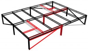
Step A: The start/end nodes of framing members are identified, mapped to a geometric coordinate, and then rebuilt within the Grasshopper/Dynamo interface. It is then important to validate the direction of framing members according to a standardized convention. Any member not drawn according to the standard must have its start/end nodes reversed. Since reactions may not be the same at either end of a member, this step is critical to ensure the accuracy of the transferred data. Now that the geometry is drawn and oriented properly, the analysis model members must be mapped to the corresponding member within the design documents. This can be done in multiple ways. The most straightforward is a simple geometric location comparison between each member’s start/end nodes and then selecting the members with the smallest aggregate absolute distance between these points. If a common origin point is not shared between the models, a model translation may be necessary.
Step B: At this point in the script, the user has enough data correctly linked to each other to discern where and by how much the analysis model deviates from the design documents. The files can then be updated so that any transferred information follows the design intent. After the necessary updates are completed, either manually or automatically, information from the analysis model can be quickly applied to the design documents by using the data mapping that was previously conducted. As a result, tasks that would have previously taken hours to complete, such as including beam end reactions as instance parameters in Revit, are now accomplished efficiently and without the risks associated with the manual transfer of vast amounts of data.
Conclusion
Computational design tools can assist structural engineers in navigating through an industry with ever-increasing quantities of highly variable data. From load application in the design phase to including beam end reactions on construction documents, these tasks must be conducted efficiently, minimizing the risk of errors.
Engineers now have access to tools that allow them to accomplish this goal with computational programming logic that would have previously only been possible with a strong knowledge of multiple computer languages. The visual programming interface that these programs use provides all engineers the opportunity to extract, process, and distribute data to improve quality control processes across the industry. These tools are no longer just for use on complex, high-profile projects. Computational programming is for all engineers searching for a way to make their everyday workflows more efficient.■