
Rebuilding the Sperry Chalet: Part 2
The backcountry Sperry Chalet was constructed over several summers in the 1910s using timbers harvested within Glacier National Park. The stone was quarried from the talus slope just uphill of the chalet. Over two feet wide at the base and tapering to sixteen inches wide at the roof level, the masonry walls consist of two interwoven leaves of argillite, a fine-grained sedimentary stone consisting primarily of lithified muds. The masonry is purposefully laid in random ashlar coursing, and the massive exterior leaf stones project by varying degrees conveying a natural aesthetic and textural ruggedness. Around the perimeter, log knee braces are supported on projecting exterior stones that act as corbels. Smaller stones and thinner mortar joints on the walls’ exposed inside faces define a more uniform finish than the exterior. Opening heads are supported by unreinforced concrete lintels on the interior and arched rowlock stone coursing on the exterior (Figure 6). Only the fire-damaged masonry chimneys and perimeter walls remained after the historic building was lost to the Sprague Fire in 2017, as described in Part 1 (STRUCTURE, May 2021). [Note: Figure numbering continues from Part 1.]

High temperatures damage metals and cementitious materials, but the effects on stone are less well known. Thermal differentials in stone are known to create fracture planes. The initial site investigation sought to understand the fire’s intensity and ascertain the extent of masonry damage. Glass, aluminum alloys, lead, iron, and steel debris were extant in the debris within the building footprint when the design team first visited the site. These materials were studied to estimate the temperature of the fire. Knowing the melting temperatures of these materials, the fire’s sustained temperature was determined to fall between 1350°F and 2100°F.
Since the fire burned from within the structure, the masonry’s exterior leaf remained essentially undamaged except at the jambs and the top of the walls. The design team mapped the intensity of the fire based on the level of damage to the interior leaf of masonry. The most intense areas of fire were at the tops of the walls and around wall openings where the most oxygen was available. The hot inside faces of the stones fractured when they were quenched during firefighting.
Most of the chalet’s stone units are naturally bedded, with their sediment layers oriented horizontally. However, there are face-bedded units, and face-bedded units turned normal to the plane of the wall that helped define the natural vernacular. Over the building’s lifespan, the face-bedded stones on the exterior had not delaminated, as is common with other sedimentary stones in cold environments. However, the stone delaminated on the wall’s inside face where the fire burned the hottest. The face-bedded stone delaminated somewhat cleanly along bedding planes to a uniform depth, the depth varying depending on the intensity of the fire. The face-bedded stones turned normal to the wall and the naturally bedded stones fractured unevenly. Fracture planes crossed bedding planes and converged within the depth of the stones to create faceted voids.
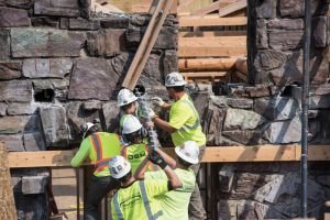
The depth of delamination varied and, in the worst cases, was just over 2 inches. Structural analysis of the wall assembly indicated that an average of 2 inches of material could be lost without compromising the wall strength for gravity and lateral loads in the new design. The masonry walls’ inside faces were first descaled of unbonded material from top to bottom. Mortar joints were raked back to match the new inner wall plane. Jamb stones that were exposed to the fire on three sides and consequently suffered through-unit cracks were replaced. The tops of the walls were reconstructed where the setting mortar between the smaller stone units had severely degraded in the fire. Replacement stones were transported by helicopter from the original quarry to the masons.
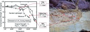
Another component of the investigation was understanding the fire’s effect on the concrete lintels. Concrete, mortar, and other cementitious materials undergo color changes when subjected to high temperatures. Color changes progressively from gray to a subtle pink color, white-gray, and finally to buff as the temperature rises. After the fire, the concrete lintels’ faces were observed to be a buff color, suggesting that maximum fire temperatures exceeded 1700°F. In one location, the concrete spalled to reveal a multicolored cross-section that provided more clues. For concrete with siliceous aggregate, the observed depths of color gradation suggested a high-temperature duration of 1½ to 2 hours and an approximate halving of concrete compressive strength in the outer 1 inch of material (Figure 7).
The fire-weakened concrete lintels were retrofitted with galvanized steel lintels. WT webs were fit into vertical slots cut into the underside of concrete lintels, and the flanges bear on galvanized plate steel at the jambs concealed by window trim. Spalled sections of concrete were patched with repair mortar.
The exterior masonry walls’ condition was unknown when the lateral design for the reconstruction was initiated. The building is classified as Seismic Design Category C. The masonry walls have abundant perforations allowing each dorm-sized room to have a window and balcony door. The historic stonework had to remain visible, eliminating common retrofitting options such as shotcrete or carbon fiber. A steel frame or brace system was similarly ruled out because of the constructability challenges they would present. Instead, the designers decided early on to use flexible wood-framed diaphragms and wood-framed shear walls as the lateral force-resisting system. These new interior walls were designed to take the full seismic demand and are founded on new reinforced concrete footings that bear directly on the natural rock below the crawlspace. This design decision created a challenge to attract load away from the stiffer existing masonry walls.
In the transverse direction, the new wood diaphragms cantilever to the outboard masonry walls. Recognizing the diaphragm’s inherent stiffness, the location of the shear walls was fine-tuned to limit the load that would be delivered to the masonry gable end walls. Although the transverse stone walls were checked to have the requisite strength to carry a tributary portion of the lateral load, they are not relied upon in the load path. The transverse lateral system was designed as though the end walls would lose integrity during a significant seismic event. The lateral design in the longitudinal direction was designed following the same philosophy.
The masonry walls’ inner and outer leaves were stitched together with a matrix of ½-inch-diameter stainless steel pins set in Hilti HIT-HY 270 epoxy adhesive that supplements the bonder stones. The pins ensure that the masonry leaves act compositely and that the walls satisfy minimum height to thickness ratios. The repaired masonry walls offer redundancy in the lateral system and resistance to eccentric loading. While the perimeter stone masonry walls are stiffer than the new interior wood shear walls, the slenderness of the masonry piers counteracts the disparity to some degree.
When the reconstruction was designed, it was assumed that the original log floor joists at the second floor cantilevered through the exterior masonry walls to form the balconies. It was discovered during the initial site visit that the original balcony framing was separate from the interior framing. The balcony joists were simple-spanning, supported only by the wall pockets and diagonal log knee braces. Without positive anchorage of the balconies through the wall into the interior floor, the original design lacked seismic connectivity. The knee braces exerted lateral thrust mid-height on the stone walls, and the framing was extremely prone to decay in the harsh environment. Formerly, the balcony framing was actively maintained and periodically rebuilt by the park to address decay conditions. A part of the design challenge was to increase the longevity of the balconies and integrate life safety.
Since the wall pockets did not align from exterior to interior, interior log joist framing was respaced to facilitate the new cantilevered joist design. The interior joists were located to exit the building in alignment with the original balcony joists to favor the historic exterior appearance. The new continuous joists are fitted with galvanized steel plate flitches (Figure 8). The flitches were designed to take the full cantilevered outer-span load, allowing the logs to stop short of the masonry where they would otherwise be prone to decay. The balcony logs act essentially as jackets that can be periodically replaced. The balcony knee braces are not relied upon for strength but are incorporated into the design to limit deflection and recreate the exterior appearance. The flitches are grouted solid into the walls, with logs tight to masonry on either side and serve as seismic wall ties that transmit masonry anchorage into the floor diaphragm.
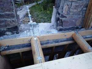
Interior log floor joists that are not part of the balconies were sized without flitches and were held short of the wall pockets to avoid decay susceptibility, bearing instead on a ledger angle. The abandoned interior pockets were grouted solid, and the steel angle was designed to double as a continuous diaphragm chord and seismic collector (Figure 9).
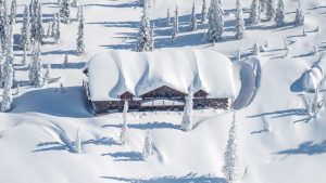
One of the most obvious structural challenges was the roof design, as the chalet is almost entirely buried by snow during the winter months (Figure 10). Stakeholders were clear in their desire to reframe the roof with exposed logs having the same proportionality as the original ones. The original roof framing was certainly undersized. It was later learned that the original roof survived the winter months via internal props installed during the end-of-season shutdown. The roof framing also relied on a set of interior knee braces along the heavily loaded purlin lines that induced horizontal point loads on the masonry end walls and interior posts.
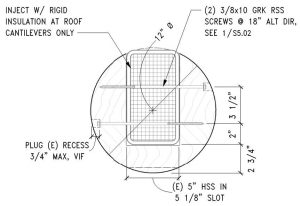
The interior knee braces were eliminated in favor of clear-spanning HSS tube steel purlins wrapped in log jackets to create a cleaner roof framing load path. Like the balcony framing design, the purlins were designed to cantilever to the rake edges without structural reliance on the exterior knee braces. The log jacketing is omitted through the plane of the wall to avoid decay and allow for periodic replacement of the outboard ends. The purlin ends are foam-insulated to lessen the potential for condensation inside the building envelope (Figure 11). The long-span log rafters and valley beams were outfitted with galvanized steel plate flitches. Unlike the balcony logs and roof purlins, the rafters are better protected by the roof, and they run uninterrupted over the top of the walls wrapped in a vapor barrier in stone saddles.
Like all successful projects, this project required commitment, teamwork, and ingenuity. It presents a valuable case study in responding to disaster with creativity and finesse. The rebuilt Sperry Chalet offers the same charm but with a more resilient backbone.■