
Brick Masonry Façades and the Structural Engineer
Structural engineers typically have had little involvement with the design of brick masonry veneers other than the selection of lintels, shelf angles, and the attachment of these supports to the structure where warranted. In most cases, this is because brick masonry veneers are generally detailed prescriptively, which does not require engineering design. However, modern designs demanding high-performance enclosures and unique façade profiles increasingly require a structural engineer’s involvement for the design to conform to code requirements while achieving the intended effect.
Prescriptive vs. Engineered
Many engineers tend to be most familiar with engineered or performance-based methods. Project-specific loads are determined under the procedures in model building codes and referenced resources such as the International Building Code (IBC) or the American Society of Civil Engineers’ ASCE 7, Minimum Design Loads and Associated Criteria for Buildings and Other Structures. Material codes, such as the American Concrete Institute’s ACI 318 (concrete), Building Code Requirements for Structural Concrete and Commentary, or ANSI/AISC 360 (hot-rolled steel), Specification for Structural Steel Buildings, are used to determine or select appropriately sized structural members.
In contrast, the prescriptive method is meant only for the most common and straightforward applications. Prescriptive provisions can only be applied when the project meets the criteria defining its application. If all these criteria cannot be met, the prescriptive requirements cannot be used, and an alternate compliance path is required. Brick masonry has historically been designed prescriptively, with architects selecting compliant components (brick units, veneer ties) and specifying the required veneer tie spacing.
Brick Veneer Construction
In the case of masonry, the term “veneer” means that the outer wythe serves as the exterior finish and transfers out-of-plane load directly to a backing but is not considered to add strength or stiffness to the wall assembly. Brick veneer is classified as either anchored veneer or adhered veneer.
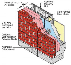
As depicted in Figure 1, anchored brick veneer consists of clay masonry units, nominally 3 inches or 4 inches wide, separated from a backing or back-up wall construction, yet secured to it and supported laterally with regularly spaced veneer ties. The masonry units must be supported by the foundation and, as required, intermediate supports such as shelf angles. In this case, the masonry only supports its self-weight.
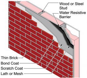
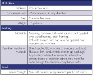
An adhered brick veneer consists of clay masonry units, typically ranging from ½ inch to 1 inch in thickness, adhered using mortar to a substrate. The substrate can consist of either lath with a scratch coat of Portland cement mortar (lath and scratch coat), cement board, or a proprietary modular panel. The substrate is mechanically fastened to a backing. Where the backing is concrete or masonry, and the surface is stable and suitably prepared, the units can be directly applied to the backing. The attachment to the backing supports the veneer both laterally and vertically. Figure 2 depicts an example of adhered veneer on lath and scratch over a light gauge frame (stud) backing. This type of adhered veneer is often referred to as “thickset.”
Brick cast into architectural precast concrete or tilt-up concrete panels does not fall into the category of veneer. It is considered a finish to the concrete panels and therefore governed by the architectural precast concrete or tilt-up concrete manufacturers’ requirements, as applicable. However, brick installed after such panels have fully cured is considered a veneer and would be designed and constructed as described herein.
Code Requirements – General
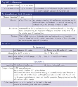
The current requirements for masonry veneer design and construction are included in the 2016 version of TMS 402 – Building Code Requirements for Masonry Structures and TMS 602 – Specification for Masonry Structures. These requirements include provisions for general design, prescriptive code, and alternative design. The 2018 IBC references the TMS 402/602 requirements for masonry veneer. Select code provisions for anchored and adhered brick veneer are summarized in Table 1 and 2.
As shown in Tables 1 and 2, there are fewer prescriptive code requirements for adhered veneers compared to anchored veneers. The code has not kept pace with the growing popularity of adhered veneer systems and the development of new proprietary technologies such as improved modified mortars and modular panel systems. Industry organizations such as the Brick Industry Association (thin clay brick) and the National Concrete Masonry Association (manufactured stone veneer) offer design guides and recommendations for these systems that can be used to supplement the code requirements. These organizations also offer technical assistance to architects, engineers, and contractors.
Anchored Brick Veneer – Corbelling
Corbelling is a technique in which masonry is projected outward or inward incrementally over several adjacent courses. TMS 402 establishes prescriptive limits on the extent of corbelling for the stability of the veneer. Each course in the corbel cannot project more than one-half the nominal unit height or one-third the nominal unit thickness. The overall horizontal projection of the corbel cannot exceed one-half the nominal unit thickness. There are no provisions in TMS 402 for corbelling adhered veneers.
Alternate Compliance Path
As noted previously, when the project in question does not or cannot conform to the prescriptive code requirements, other compliance paths must be used to meet the code. The veneer chapter in TMS 402 includes anchored veneer alternative design provisions that serve as a substitute compliance path in lieu of the prescriptive provisions. These alternative design provisions consist of an engineered rational design method that applies the following four requirements or guidelines:
- Loads shall be distributed through the veneer to anchors (as applicable) and the backing through the principles of engineering mechanics
- Veneer stability must be maintained through limits to out-of-plane deflection
- The veneer need not be subject to the flexural tensile strength provisions of the Allowable Stress Design and Strength Design chapters in TMS 402.
- The general requirements for veneer must be met, along with the requirements for veneer not laid in running bond in the case of anchored veneer and the seismic prescriptive provisions.
The use of the alternative design provisions does not need to apply to the entire façade, only the portions that exceed the prescriptive code limitations. For instance, if a building has a prominent cornice, but the remaining brickwork meets the prescriptive requirements, only the cornice must comply with the alternative design requirements.
Examples
The following examples describe common situations in which a structural engineer will need to become involved in brick veneer design and provide conceptual solutions to these situations.
Case 1 – Continuous Insulation
Anchored Veneer. The maximum air space dimension in the prescriptive code requirements results in a maximum 5-inch thickness of insulation that can be installed. Architects wishing to follow high-performance enclosure design principles that recommend superinsulation can find the limit of 5 inches restrictive. Where the air space/drainage cavity exceeds the prescriptive limit of 6⅝ inches, there are two primary options: use custom or semi-custom veneer ties or modify the backing to reduce the air space. The use of custom/semi-custom veneer ties is discussed in Case 3.
To modify the backing and reduce the air space to prescriptive dimensions while not excessively restricting the extent of insulation, consider vertical battens aligned with the studs that project into the air space/drainage cavity. The structural engineer would size the battens and design their connection to the studs or other framing to ensure continuity of the load path from the veneer to the structure. Because the battens would be located within the typical wet zone of the wall assembly, the batten material should be appropriate for that exposure, or instead, installed behind the water-resistive barrier and detailed accordingly to resist moisture.
Adhered Veneer. Placing continuous insulation behind adhered veneer has only recently become more common. Including continuous insulation within the wall assembly requires placing the weight of the veneer further from the backing where typical anchorage details for adhered veneer systems cannot handle the additional eccentricity. The IBC includes tables in Chapter 26 for fastening requirements over foam plastic sheathing. Still, many cases require the design of these connections by a structural engineer due to the cladding weight or the desired thickness of insulation.
Due to the lack of restraint from the insulation, the fasteners are subjected to bending because of the stand-off between the load and the anchorage of the fastener into the backing. This addition of bending to the expected tension and shear forces will likely require larger fasteners than expected for the weight of the veneer. Since these same fasteners carry the gravity load of the system in addition to the lateral load, it is recommended to limit the vertical deflection of the fasteners to ⅛ inch.
Case 2 – Corbelling
The prescriptive limits for corbelling may not be satisfactory for designs that feature projecting brickwork. Further, the prescriptive corbelling limits are often misunderstood. In projects with sloped or slanted walls, designers sometimes assume that an angled backing following the slope of the corbel absolves them from complying with the limits because the air space/drainage cavity is consistent in dimension. In other cases, the designer only implements the individual projection limits and omits the overall horizontal projection limit, not realizing that both conditions must be met.
The overall horizontal projection limit is critical because, when corbelled brickwork projects beyond the footprint of the brick course at the base, the weight of the brickwork creates an overturning moment that either pulls the veneer off the wall or pushes it inward toward the backing. While veneer ties can restrain this overturning moment, it is critical to understand that the veneer ties are only intended to transfer the prescriptive lateral load to the backing and are manufactured accordingly. By using the veneer ties to restrain brickwork corbelled beyond the prescriptive limits, the additional tension or compression load from the overturning moment can potentially exceed the capacity of the ties. The structural engineer should coordinate with the veneer tie manufacturer to determine whether the specified veneer ties will be adequate for the intended corbelling effects. In many cases, more frequently spaced ties or veneer ties with heavier gauge components are sufficient to accommodate corbelling beyond the prescriptive limits.
Another consideration in corbelling that requires evaluation is the support of the brickwork until mortar cures when the overturning moment caused by corbelling will be restrained by the veneer ties. The load capacity of typical veneer ties relies on their bond and engagement with hardened mortar. Many projects with extreme corbelling incorporate custom veneer ties that mechanically engage the brick units instead of relying solely on embedment in mortar.
Adhered Veneer. As noted previously, TMS 402 does not include provisions for corbelling in adhered veneers. However, thin units intended for adhered veneer applications are available in various thicknesses and designers have combined units of different thicknesses such that the appearance of corbelled brickwork or a pattern of projections is achieved. These cases must be addressed through the alternative design provisions in TMS 402. Similar to the case of installing adhered veneer over continuous insulation, the engineer should consider the variation in unit thicknesses by accounting for the additional overturning forces and non-uniform distribution of forces within the anchorage design.
Case 3 – Dimensional Errors
The author received an inquiry about a project where the construction team found that the completed cold-formed steel stud backing did not correspond with the intended location of the exterior face of the anchored brick veneer. The dimensional bust resulted in an actual air space dimension of 8½ inches compared to the originally specified 4 inches. In order to restore an air space less than 4⅝ inches in width, the construction team proposed adding a second wythe of masonry on the interior side of the brick, attached to the backing using veneer ties and connecting the wythes together with joint reinforcing, but not compositely. Expansion or relocation of the backing was not feasible.
The proposed solution represented a misunderstanding of the prescriptive code limitations. The addition of the second wythe of masonry would reduce the air space/drainage cavity within the prescriptive code dimension, but the creation of a “double veneer” violates the limits on veneer thickness in addition to creating an unusual assembly with complex behavior. While the alternative design provisions would allow for an engineered double wythe veneer, the recommended solution involved eliminating the inner wythe of masonry and using customized veneer ties. This solution still required using the alternative design provisions because the dimension of the air space exceeded 6⅝ inches, but upgraded ties were a simpler and faster option that better suited the construction schedule.
Veneer ties are proprietary products designed primarily for prescriptive code provisions. However, veneer tie manufacturers perform their own development and testing of the ties. As a result, they can upgrade wires and plates beyond the sizes used in the typical product line when higher capacities and longer ties are needed to create a semi-custom veneer tie. For this scenario, the structural engineer should coordinate directly with the veneer tie manufacturer to discuss available options and obtain test data for review.
Conclusion
Increasingly, structural engineers may find themselves facing complicated brick veneer façades. Still, it need not be a cause for concern due to flexibility in the alternative design provisions and known approaches for common applications. To date, the current provisions have been used successfully on a variety of projects; however, the industry recognizes that the veneer code requirements could be improved. The code cycle for the 2022 version of TMS 402/602 is nearing completion and will include an extensive reorganization and expansion of content for masonry veneers to provide more resources for engineers. Examples include a new engineered method developed for anchored veneer to serve as an intermediate step between the prescriptive requirements and full rational design, as well as tables that more concisely present the prescriptive anchored veneer requirements and present prescriptive solutions for adhered veneer applied over drainage cavities or continuous insulation of various dimensions.■