
Structural engineering education includes fundamental principles of mechanics of materials and structural analysis that help engineers to understand and design structural members and systems. Occasionally, it is necessary to wander into design considerations outside of the structural realm, such as corrosion protection and serviceability. Still, rarely are structural engineers taught to prioritize constructability as a primary focus of structural design. This consideration often comes with experience as it is learned that the most efficient or elegant structural solution is not always the easiest to construct or (arguably more important) the least expensive. Structural engineers’ limited education on masonry materials and limited exposure to masonry construction processes can magnify installation issues. This article highlights how engineers can avoid some of the most common constructability issues with modern structural masonry.
What is the best way to understand masonry constructability concerns? Ask masons! The authors surveyed masons and masonry experts across the country to identify common field issues that can help engineers develop more constructible masonry design practices. Three of the most common themes from the survey are:
- Detailing – Provide sufficient detail in structural drawings.
- Bar Congestion – Avoid the most common bar crowding conditions.
- Different Materials and Trades – Limit conflicts, differing tolerances, and trade coordination challenges by limiting the integration of other structural materials into masonry walls.
Other common concerns identified by the survey that should be kept in mind during design are:
- Control Joints – The Building Code places design responsibility for control joints on the designer; contractors should not be responsible for layout.
- Mason-Preferred Bar Size – Based on the survey, 78% of masons prefer #5 bars for vertical reinforcement in partially grouted walls, with #6 bars being the second choice for most. When larger bars are specified, lap lengths and bar weights become concerns for masons.
- Bar Size Selection – Consider using only odd bar sizes (#3, #5, #7) for ease of distinguishing size on site with a quick glance. Also, if #5 bars are selected for vertical reinforcement, using #5 bars for lintel and bond beam reinforcement limits the need for ordering and organizing different bar sizes on site.
- Mortar Type – Consider Type N mortar unless seismically restricted (yes, even in structural walls) to increase water resistance, improve workmanship, and decrease cleaning effort. f´m is actually not usually very important in structural design since tensile and shear reinforcement generally dictate capacity. Read Appendix X1 of ASTM C270, where Type N is the recommended mortar for load-bearing walls!
- Local Materials – Ask your local block supplier about local block strengths since they often depend on local aggregate availability; avoid specifying excessive (expensive) f´m. For example, Colorado has lightweight aggregate readily available with typical block strengths around 2,200 psi. When paired with type N mortar, this block yields an f´m value of about 1,830 psi using the unit strength method. By comparison, typical block strengths of CMU produced with normal weight aggregate common to areas in the Midwest are often around 3,000 psi, providing an f´m of approximately 2,120 psi when type N mortar is specified.
- Designing for Modularity – Rule of thumb: dimensions should be divisible by 8 inches, including rough openings. Minimizing the number of cuts a mason is required to make can provide savings in both cost and construction schedule. NCMA Tek Note 05-12 explains that masonry openings are typically 4 inches wider and 2 to 8 inches taller than doors and windows to allow for framing and window sills. This means that a modular opening size of 40 inches can usually accommodate the installation of a 36-inch standard-sized door, for example.
- Means and Methods – The masonry Code and Specifications allow the mason to choose low-lift vs. high-lift grout placement and the means of locating reinforcement (e.g., bar positioners).
Detailing
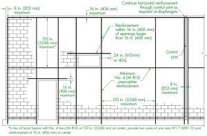
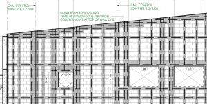
When thinking of how much detail is adequate for masonry drawings, consider how a mason uses the construction documents to lay out a single wall with control joints, openings, and bond beams. Do the drawings require a mason to assemble information from numerous details, tables, and (worst of all) specifications to configure a simple wall? A typical wall elevation that shows various wall conditions (doors, windows, control joints, etc.) can greatly improve a mason’s understanding of how various reinforcing requirements interact. An excellent example of this type of drawing can be found in the National Concrete Masonry Association (NCMA) Tek Note TEK 14-18B (Figure 1). Even better, incorporating elevation drawings for the entire structure provides specific reinforcement information and virtually eliminates conflicts (Figure 2). Ensure that your details include all dimensions, including dimensions (or acceptable ranges of dimensions) for reinforcement locations in plan, elevation, and section.
One of the most common omissions from structural drawings is sufficient lintel detailing. Lintel details are often omitted from the drawing set altogether. When they are present, they are often limited in terms of reinforcement location, bearing length, and lintel height. One tip to simplify your masonry lintel design is to increase lintel depths to ensure that all lintel span-to-reinforcement-depth ratios are less than or equal to 8. Increasing lintel depth is a relatively easy and inexpensive modification that ensures that you do not need to perform complicated deflection checks on the lintels.
Bar Congestion
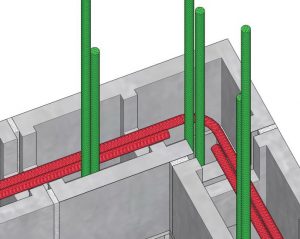
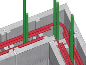
Another common constructability concern with reinforced masonry is bar congestion in the cells. Congestion is not always obvious in the design process because reinforcement is drawn as single dots or lines. However, especially in low-lift masonry construction, wall reinforcement is lapped at relatively tight and regular spacing. It is common for the length of reinforcement that is lapped to be much greater than the length where only a single bar is present. For this reason, a single bar on the drawings should generally be considered to require the installation of two bars in the field. One of the most common areas of bar congestion occurs at wall corners since these areas include vertical bar laps and corner bar laps at bond beams. In addition to reinforcement, mortar protrusions can even further restrict cell area. Designing bond beams with only one bar is critical to avoid congestion issues and associated grout consolidation concerns at corners (Figures 3 and 4).
Using a single bar centered in a cell has a variety of significant benefits. Besides avoiding congestion issues, lap lengths are reduced substantially for single bars centered in cells since the masonry code increases the required lap length when cover is reduced. Using a #5 bar centered, versus at the face shell, reduces the lap length by more than 50%, from 49 to 19 inches. Increased lap lengths add costs due to materials and labor and can even lead to laps that are longer than grout lift heights, which creates a nasty constructability problem. To illustrate the advantages of using a single bar centered in a cell, consider a typical wall using an 8-inch CMU with an f´m of 1,750 psi (2,000 psi block with Type N mortar). Which wall would have the larger capacity: one #5 bar centered in the cell or two #5 bars, one at each face of the cell? While it may be evident that the wall with two bars has a greater capacity, is this an efficient and constructible design? The two-bar design has a capacity 69% higher than the single-bar design. However, due to increased lap lengths required for the two-bar design, the weight of the reinforcement used is increased by 162%. While the two-bar design has a higher capacity, the increase in strength is not proportional to the amount of reinforcement or labor required to build this wall. And, the additional congestion makes construction issues more likely.
Different Materials and Trades
It is common to encounter designs where various structural materials are integrated into masonry walls. Perhaps the most frequent examples are steel lintels and steel columns embedded in masonry. Embedding other structural materials into the field of a masonry wall can create several constructability concerns. First, there is often inefficiency because of coordinating trades. If a mason must stop work to allow an ironworker to erect steel, this interruption breaks the typical workflow. It can lead to delays, discontinuities in grout lifts, and conflict between trades. This can be further exacerbated by the need for weld inspections or field treatments of embedded elements.
Additionally, embedding non-masonry materials in masonry walls often significantly increases time and labor for masons in placing units around the embedded objects. For example, if a 13-inch-wide steel column is placed in line with a masonry wall, it is likely that every single masonry unit on both sides of the column will need to be cut to fit the masonry around the column. Similarly, a 10-inch-deep beam or lintel element will require cutting down unit heights to maintain coursing, and masons frequently must place faceshells (soaps) around embedded elements for fire protection or to conceal these embedded elements, which is labor-intensive and inefficient.
Finally, differing construction tolerances for various materials can lead to conflicts between masonry and embedded elements. Although masonry industry codes and guidelines generally permit out-of-plumb variations of ± ¼ inch in 10 feet, it is very common for project specifications to limit visible corners and edges to a variation of ± 1⁄8 inch in 10 feet. This is an incredibly small permissible variation compared with other construction materials. The thicknesses of connection plates or even bolt heads in steel elements generally exceed 1⁄8 inch, and wood member dimensions may vary by more than 1⁄8 inch from piece to piece (not to mention bowing and warpage). Often, masons are put in an untenable position where they must maintain tight tolerances on the masonry despite variation in elements that their work is resting on or adjacent to. These awkward interfaces can also be stressed when differential volumetric behavior, such as shrinkage of block or thermal expansion of steel, push and pull on the different materials.
As a structural engineer, consider whether these constructability concerns can be avoided by using all-masonry construction. Modern reinforced masonry has excellent compression capacity, so using a pilaster instead of a steel column is generally more efficient and economical. Similarly, using masonry lintels rather than steel tends to expedite projects and reduce trade conflicts.
Conclusions
In conclusion, there are some relatively simple changes to structural drawings, such as adding typical elevation views, detailing lintels, using single bars for vertical reinforcement and bond beams, and limiting non-masonry embedded structural materials, that can help transform your relationship with the masons building your projects from a conflict to collaboration. So, love your local mason today!■