
A Case Study in Panelization of a Complex-Shaped Hybrid Structural Framed Precast Building
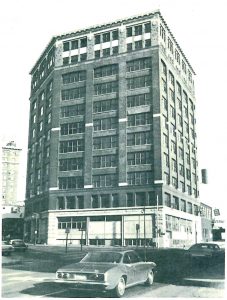
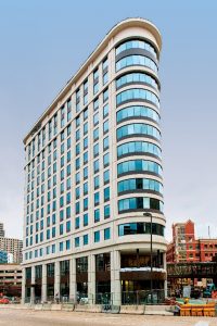
As new structures rise above city streets, the architecture is often in conflict with the historical style of surrounding buildings. This is not the case with the 10-Ionia project, located on a site with a deep history. For 10-Ionia, the new architecture was chosen to complement the surrounding structures and conform to a unique triangular site bound by three streets with very active traffic. Originally the Rindge Building site from the late 1800s, it was later used as a parking structure containing street-level commercial areas such as a candy store and cigar shop. This building was a structural steel building with a brick exterior and a unique geometric shape. The building was demolished on May 4, 1978. In early 2016, planning began on a new destination hotel designed as an icon for the City of Grand Rapids, MI, incorporating the architectural style from years past using today’s technology and materials.
Materials Selection
The Architect of Record for the project, Yamasaki® Architects, proposed using precast concrete to the Owner as an alternate to cast-in-place concrete or structural steel to address various challenges, which were later validated in collaboration with the precaster, Kerkstra. First, the triangular building shape resulted in connection geometries that would have made connections using CIP concrete or structural steel complicated and expensive. Second, the steel solution required a higher floor height, which meant an increase in façade cost. Also, the CIP concrete solution was inefficient due to the formwork required for the triangular building and the need to clad the cast concrete to provide for a final finish. The precast solution provided the ability to use a thinner external bearing wall that maximized the depth from the exterior wall to the core; it was essential to adapt the Residence Inn® unit plans to the small footprint.
The precast solution also provided the structure with an architectural finished panel at the first two levels using special aggregates and a special finish technique to provide the Limestone color. The upper floor facades constructed in structural precast concrete were stained for an economical solution. Taking advantage of the latest concrete precast technology and the economies of producing large-scale repetitive elements, the panels provide a sense of scale and quality generally associated with historic masonry structures. Sufficient detail to match the surrounding historic district was achieved using a system of offsets, belts, and reveals.
Design Approach
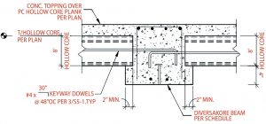
Originally conceptualized as a cast-in-place structure, maintaining a similar structural system depth at or near a post-tensioned slab was required. The selection of a hybrid-framed hollow-core system was made, allowing the floor plate to span 30 feet from the central core to the exterior wall without intermediate support using 8-inch hollow-core slabs with a 2-inch composite topping (Figure 1). Hybrid framing combines the benefits of three structural systems to provide a unique structural system of steel, cast-in-place, and precast. This U-shaped steel form provides a T-shaped beam and composite column design that bonds steel and concrete with significantly enhanced performance characteristics. The use of precast floor members, exterior architectural walls, and shear walls, along with a cast-in-place framing fill and plank topping, provide enhanced span-to-depth ratios, shallower beam depths, and smaller column footprints.
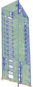
Following the building’s geometry, the structural core of 10-Ionia is also triangular, which provided challenges for the design. The geometry of the structure did not allow for a conventional shear wall or moment frame lateral resisting system, as is most common in total precast structures. Thus the triangular core was chosen to carry the lateral loads of the structure. The core was framed with twelve precast walls per level, connected at each vertical joint with a vertical cast in place pour strip (full height of structure) and grouted mechanical dowels at each horizontal joint. The result was a structure that behaves monolithically and was designed and analyzed as an emulated cast-in-place triangular tube. RISA 3D, a structural engineering design and analysis program, was used to model the emulated structure to determine behavior, shear flow through the vertical pour strips, and flexural and shear design of the members (Figure 2). Numerous block-outs through the precast walls for other trades further complicated the analysis.
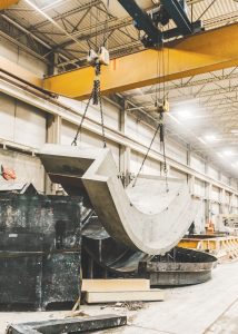
The detailing of the structural geometry and intricate architectural façade (also load-bearing) was accomplished utilizing three-dimensional modeling by both the Architect and Precast Design Team. The Architectural Team utilized Revit, and the Precast Design Team utilized Edge (a three-dimensional modeling software that sits on top of Revit, designed especially for precast concrete detailing) to create the construction model, precast concrete structure drawings, and production formwork details. The BIM coordination and modeling of the structure with Edge proved vital in the final structural design of the core and procurement of the complex forms (Figure 3) required for the exterior façade. Many openings in core walls had to be coordinated to either miss critical reinforcing in the panel or design the reinforcing around them. This was accomplished with weekly coordination meetings where the openings were reviewed in the model and decisions made as to the correct course of action to ensure functionality and structural integrity. Implementing BIM at the beginning of the project helped successfully coordinate the complicated geometry and needs of other trades.
Erection Considerations
The building was built such that each floor was plated, composite topping added, and connections and steel member infill completed as the structure went vertical. This allowed for the occupancy of the floor below by other trades during non-erection times. The Erector had a conventional ground-control lattice boom crane with a luffer in a tower configuration. This allowed the crane to move along the East side of the structure to access each of the North and South side corners and remain within the chart of the crane. This crane did not have two lines, restricting the method in which the panels were shipped. Each panel had to be shipped vertically such that the crane could pick the piece directly from the trailer. Also, most of the exterior walls had windows pre-installed in the precast, adding to the gentle nature of the installation. The precast plant rolled all panels vertically before final finishing and racking. Radius panels had special attention paid to the picking inserts’ location to ensure that they did not roll out of vertical such that they could not be installed without additional effort.
Lessons Learned
Project coordination between the design team, precast fabrication plant, and the Erector was key to this project’s success. During the planning of this project, the precast fabrication labor leads were deeply involved in the means and methods of the forming system to be used, how to remove the pieces, roll the pieces, and eventually ship pieces with minimal detrimental impacts. Plant logistics, labor balancing, and yard logistics were part of the success of a completed panel that was an architectural precast fully-glazed wall section. The precast manufacturing staff also had to engage and manage structural components not typically used with precast structures. This integration and assumption of responsibility opened the project to the systems selected for the core walls, exterior walls, and floor plate. Had the hybrid framing not been introduced, a typical precast beam and column system would have proved too invasive to the building’s floor floor-to-floor height.■
Project Team
Owner: Hinman, Grand Rapids, MI
Structural Engineer: DCI Engineers, Austin, TX
Architect: Yamasaki, Detroit, MI
General Contractor: Wolverine Building Group, Grand Rapids, MI
Precast Specialty Engineer: PTAC Consulting Engineers, Pensacola, FL
Steel Framing Engineer: Diversakore, Atlanta, GA
Steel Fabricator: Premier Steel, Glenpool, OK
Precast Concrete Subcontractor: Kerkstra, Grandville, MI
References
Furniture City History by the Grand Rapids Historical Commission (unknown) APA Citation. Rindge Building. Retrieved from www.furniturecityhistory.org/architecture/4734/rindge-building.
History of Grand Rapids.org by the Grand Rapids Historical Commission (October 12, 2011) APA Citation. Parking in the Air. Retrieved From www.historygrandrapids.org/audio/2559/parking-in-the-air.
Grand Rapids History & Special Collections, Archives, Grand Rapids Public Library, Grand Rapids, MI. Collection 287 Betty Giboout Real Estate Listing Cards, Father Morrow Series Box 7: 10-22 Ionia Real Estate Card. www.historygrandrapids.org/document/2671/ionia-nw
International Building Code, International Code Council, 2012 Edition, (IBC 2012).
Building Code Requirements for Structural Concrete and Commentary, American Concrete Institute, 2011 Edition, (ACI 318-11).
Guide to Emulating Cast-in-Place Detailing for Seismic Design of Precast Concrete Structures, American Concrete Institute, 2009 Edition, (ACI 550.1R-09).
Design Loads on Structures during Construction, American Society of Civil Engineers, 2013 Edition (ASCE/SEI 37-13).
Minimum Design Loads for Buildings and Other Structures, American Society of Civil Engineers, 2010 Edition (ASCE/SEI 7-10).