
Soil-structure interaction (SSI) can make a substantial difference in how buildings behave during earthquake shaking and how they should be designed. Yet, there is relatively little implementation of SSI effects by practicing structural engineers. Provisions are available in ASCE/SEI 7-16, Minimum Design Loads and Other Criteria for Buildings and Other Structures, and in ASCE/SEI 41-17, Seismic Evaluation and Retrofit of Existing Buildings, that can be used to address SSI. However, they can be hard to follow, and limited guidance is available. To help engineers, FEMA has funded a project managed by the Applied Technology Council (ATC) and identified as ATC-144, which is nearing completion. The output from this effort includes the development of a design guide of examples, entitled FEMA P-2091, A Practical Guide to Soil-Structure Interaction.
The design guide is intended to help practicing engineers know when incorporating SSI would be important and to provide examples of how to implement different SSI techniques. It describes situations where SSI effects can reduce or increase demands on the building or simply change the pattern of yielding in the foundation and superstructure. It covers period lengthening, foundation damping, base slab averaging, embedment effects, soil flexibility, and modeling of basements, and it includes worked design examples for a two-story braced frame building and a 12-story concrete building.
This article reviews situations where SSI is important; describes the design guide’s purpose, scope, target audience, and topics covered; and provides practical tips for effective implementation of SSI. The ATC-144 project also included an in-depth analytical exercise to explore and validate SSI provisions and the development of updates to the code provisions. These are not addressed here due to article size limitations.
Situations Where SSI is Important
The following situations show where SSI can make a substantial difference in how buildings behave during earthquake shaking and how design forces can be affected. Note that figures are taken from the forthcoming FEMA P-2091 unless otherwise noted.
Large Building Footprints
Building footprint size has been shown to correlate with spectral demands, primarily in the shorter period range. The larger the building, the greater the reduction in short period spectral response. This is due to the kinematic interaction effects of base slab averaging (Figure 1).
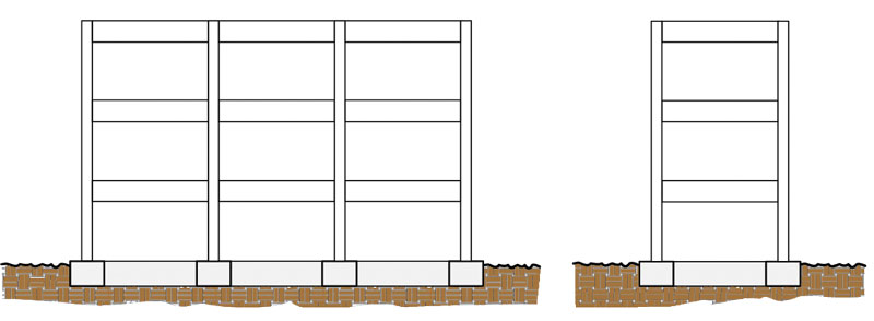
Figure 1. The building on the left with a larger footprint will have a lower design base shear coefficient than the building with a smaller footprint on the right.
Substantial Foundation Embedment
Foundation embedment has also been shown to correlate with spectral demands, primarily in the shorter period range. The deeper the embedment, the greater the reduction in short period spectral response. This is due to the decrease of ground motions with depth, which is a typical feature of site response (Figure 2).
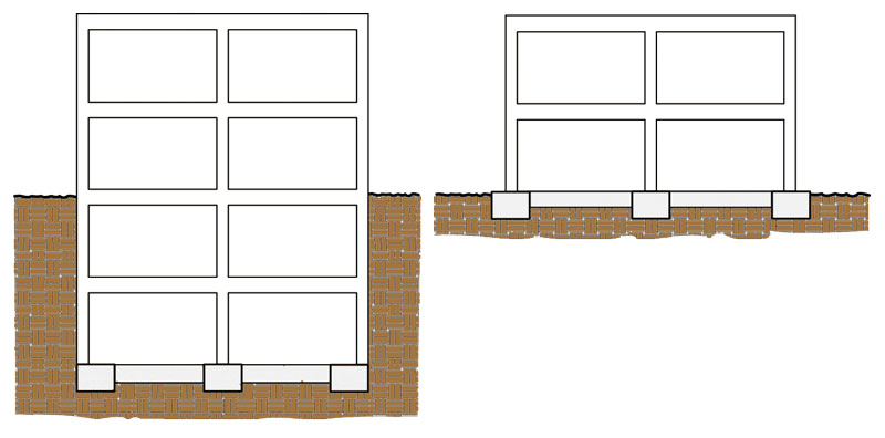
Figure 2. The building on the left with a deeper foundation embedment will have a greater reduction in the design base shear coefficient than the building on the right.
High Structure-to-Soil Stiffness Ratios
When the structure is relatively stiff compared to the soil, foundation rotation can occur, adding to structural displacements and increasing or lengthening the fundamental period of the structure. The increase in period can affect the associated spectral accelerations used in design. This effect commonly occurs in buildings with concentrated lateral force-resisting systems, such as reinforced concrete shear walls and steel braced frames, which are supported on localized foundation elements. Conversely, for buildings with wide, stiff foundations and relatively flexible superstructures, the impact of soil flexibility is typically relatively small.
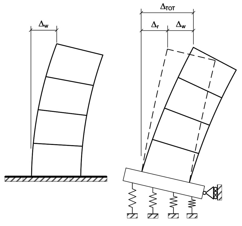
Figure 3. A structure where soil flexibility will have a significant impact on the lateral displacement and fundamental period of the structure.
Figure 3 shows an example of a concentrated cantilever shear wall and foundation system, where including soil flexibility will increase the fundamental period of vibration. The roof displacement of the shear wall itself is shown in the left as Δw. In Figure 3 on the right, the vertical flexibility of the soil is represented by a set of springs. During lateral displacement of the superstructure, there will be vertical displacement of the springs and foundation rotation. The drift from rocking is shown in Figure 3 on the right as Δr. The increase in displacement correlates with an increase in the fundamental period for the structure.
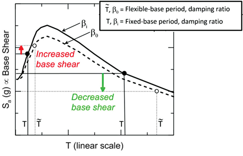
Figure 4. Significant impacts of period lengthening and foundation damping on spectral response (from NIST GCR 12-917-21).
Figure 4 shows the potential impact on changing the period in a response spectrum analysis. The period with the fixed base model is denoted as T, and the period with soil flexibility is denoted as T ˜. Two cases are shown. In the short period case, the structure is very stiff, and the increase from T to T ˜ results in climbing up the response spectrum and an increase in spectral acceleration. In the long period case, the structure is more flexible, and the increase in period results in a reduction in spectral acceleration. Figure 4 also shows the impact of foundation damping on reducing spectral response.
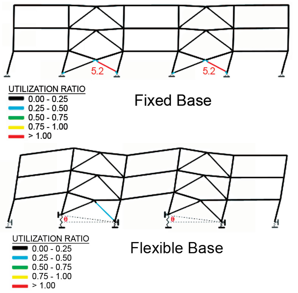
Figure 5. The significant impact of soil flexibility on a coupled braced frame system.
Foundation Rocking
Structures with concentrated coupled vertical lateral force-resisting systems can behave much differently when soil flexibility is introduced. Figure 5 shows a nonlinear static (pushover) analysis example from the seminar slides that accompanied the FEMA P-2006 design guide. In the fixed base model, the mechanism is buckling of the compression brace in the lowest story, and the brace is highly overstressed. In the flexible base model, where vertical springs are located under each column, the braced frames rock, and the system has sufficient capacity to resist the demands. Note that, in the flexible base model, the ends of the beams linking the frames have higher rotations than they do in the fixed base model.
Details on the SSI Design Guide
The overall goal of the design guide is to present information regarding SSI as implemented in code provisions but in an easy-to-understand, concise format targeted towards practicing engineers. The purpose of the design guide is (1) to help practicing engineers know when incorporating SSI would be important, and (2) to show examples of how to implement different SSI techniques.
Target Audience
The primary target audience for the design guide is practicing engineers who are familiar with seismic design using ASCE/SEI 7 but who have little to no experience with SSI. A secondary audience is engineers who have some experience with some SSI techniques, such as using springs, but may need advice on other SSI techniques they have not utilized.
Scope and Organization
The design guide covers the SSI topics in ASCE/SEI 7-16 Section 12.13 and Chapter 19. The focus is on techniques that practicing engineers can use. It is organized into the following chapters.
- Chapter 1, Introduction, introduces SSI terminology; covers the purpose, scope, and target audience for the Guide; and summarizes some key high-level advice on SSI implementation.
- Chapter 2, Situations Where SSI is Important, provides an expanded discussion of situations that engineers commonly encounter where SSI can impact the forces used in design and the way the structure responds to earthquake shaking.
- Chapter 3, Rule-of-Thumb Test for Inertial SSI Significance, describes a simple test that can be used at the start of a project when only very limited information is available to help determine if using SSI will be likely to make a difference in results. The rule of thumb is targeted at inertial interaction and does not provide information about the potential significance of kinematic interaction.
- Chapter 4, Base Slab Averaging, addresses how the interconnectivity of the foundation can help reduce the demands into the structure. It provides examples of common foundation and slab-on-grade situations, and whether base slab averaging can be used.
- Chapter 5, Embedment Effects, discusses how foundation embedment can reduce the demands on the structure.
- Chapter 6, Foundation and Soil Flexibility, reviews different methods for adding vertical and horizontal springs to represent soil flexibility.
- Chapter 7, Period Lengthening, covers provisions for how soil flexibility leads to period lengthening in the structural response and the resulting impact on seismic demands.
- Chapter 8, Foundation Damping, shows how and when to apply two types of foundation damping – radiation damping and soil damping – that can reduce demands on the structure.
- Chapter 9, How to Model a Basement, discusses different accurate but straightforward analytical approaches to modeling basements.
- Chapter 10, Conclusions and Recommendations, summarizes key points regarding SSI discussed in the design guide and provides recommendations on revisions needed to code SSI provisions and further SSI studies that should be undertaken.
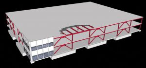
Figure 6. Two-story braced frame example in the design guide.
- Appendix A, Short Building Example, provides a detailed example of applying different SSI techniques for a two-story steel buckling-restrained braced frame building, shown in Figure 6. The building is founded on spread footings, and the equivalent lateral force method is used for design. SSI topics include implementation of soil springs, change in response mode, and reduction in seismic demands due to foundation flexibility, soil flexibility and damping, and base slab averaging.
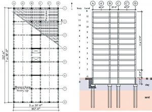
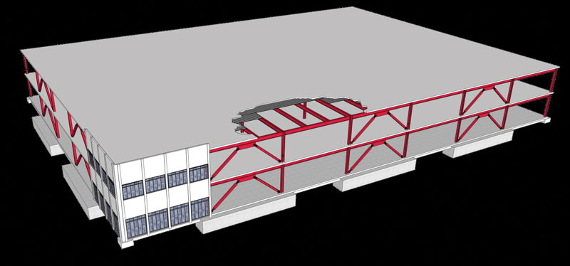
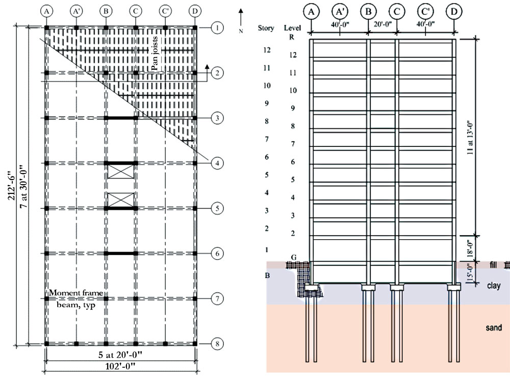
Figure 7. Twelve-story concrete building example in the design guide.
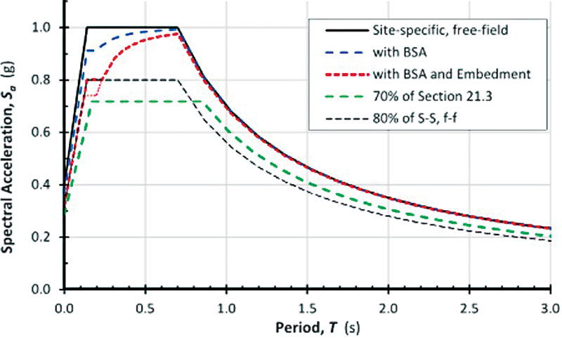
- Appendix B, Tall Building Example, provides a detailed example of applying different SSI techniques for a 12-story concrete building that has a moment frame in one direction and a dual system with a moment frame and shear wall in the other direction. It is founded on piles, and the modal response spectrum method is used for design. It includes variations with and without a basement. SSI topics covered include reduction in design demands due to base slab averaging and foundation embedment, adjustments to demands from period elongation and foundation damping, and impacts of limitations imposed by ASCE/SEI 7-16 provisions. Figure 7 shows a plan and a section. Figure 8 shows the free-field response spectrum without SSI, the reductions that base slab averaging and foundation effects provide, and the minimum floor on allowable reductions.
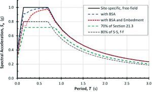
Figure 8. Design response spectra for the 12-story example building.
Tips for Understanding and Implementing SSI
Based on experience in performing SSI analyses, the following general observations are offered. These observations are discussed in detail in the design guide.
- SSI is not that difficult to implement.
- SSI is typically iterative, so it may require additional rounds of analysis to converge on the final solution, as compared to a fixed base analysis.
- SSI typically reduces the seismic demands that are used for design. Still, there are unusual cases with site-specific response spectra where demands can increase because period elongation may lead to climbing up the response spectrum with increasing levels of spectral acceleration.
- Adding foundation flexibility to a model can affect how the building behaves in some situations and associated deformation patterns, particularly for situations where foundation flexibility would lead to the rocking of shear walls or braced frames in the superstructure. This can increase shear and/or flexural demands in certain structural elements relative to what would be evaluated from fixed base analyses.
- Effective shear wave velocity, vs, is a key parameter in several SSI equations and techniques. The effective shear wave velocity differs from the low strain shear wave velocity, vso, used for site classification in ASCE/SEI 7-16 Chapter 21. Modifications are made based on soil type, site spectral acceleration, and the depth of importance. The design guide provides guidance on this subtle, important issue.
- There are several code provisions, both in ASCE/SEI 7-16 Chapter 12 and Chapter 19, that can limit the extent of SSI reductions that can be utilized. These restrictions may be discouraging the application of SSI and lack a strong technical basis.
- Although ASCE/SEI 7-16 is the standard that is referenced and used in the design guide examples, ASCE/SEI 41-17 has a similar set of SSI provisions. In some cases, ASCE/SEI 41-17 has more relaxed requirements and limitations regarding the use of SSI. The design guide highlights these differences.
Conclusion
FEMA P-2091 will provide a helpful guide to practicing engineers on demystifying and simplifying the world of SSI. The design guide will be available for free on FEMA’s publication website later this year.■
SSI Terminology
Free-field motion: Motion at ground surface in absence of structure and its foundation.
Foundation input motion: Motion that effectively excites the structure and its foundation.
Kinematic SSI: The modification of free-field ground motion to foundation input motion as a result of spatial variability in the free-field motions. Effects include the following:
- Base slab averaging: Kinematic SSI of a shallow (nonembedded) foundation caused by wave incongruence over the base area.
- Embedment effects: Kinematic SSI embedment effects in which foundation-level motions are reduced as a result of ground motion reduction with depth below the free surface in structures with embedded foundations.
Inertial SSI: The dynamic interaction between the structure, its foundation, and the surrounding soil caused by the foundation input motion. Effects include the following:
- Period lengthening: The increase in the building period due to foundation flexibility.
- Radiation damping: The damping in the soil-structure system caused by the generation and propagation of waves away from the foundation, which are caused by dynamic displacements of the foundation relative to the free-field displacements.
- Soil damping: The hysteretic (material) damping of the soil, similar to viscous damping in the superstructure.
References
ASCE, 2017a, Minimum Design Loads and Associated Criteria for Buildings and Other Structures, ASCE/SEI 7-16, Structural Engineering Institute of the American Society of Civil Engineers, Reston, Virginia.
ASCE, 2017b, Seismic Evaluation and Retrofit of Existing Buildings, ASCE/SEI 41-17, Structural Engineering Institute of the American Society of Civil Engineers, Reston, Virginia.
Braund, M., 2019, FEMA P-2006 Training: Steel Braced Frame, Structural Engineers of California Lecture Series, PowerPoint presentation slides.
FEMA, 2018, Example Application Guide for ASCE/SEI 41-13 Seismic Evaluation and Retrofit of Existing Buildings with Additional Commentary for ASCE/SEI 41-17, FEMA P-2006, prepared by the Applied Technology Council for the Federal Emergency Management Agency, Washington, D.C, June.
NIST, 2012, Soil-Structure Interaction for Building Structures, NIST GCR 12-917-21, prepared by the Applied Technology Council and the Consortium of Universities for Research in Earthquake Engineering for the National Institute of Standards and Technology, Gaithersburg, Maryland.