
Unexpected and Unfortunate Events Leading to Structural Failures
The role of structural design professionals is often complex, starting early in the conceptual phase and continuing until after project completion. From the onset, they knead architects’ visions for space and form into a stable reality. Throughout, they are navigating imperfect sites they did not select, maintaining restrictive budgets they did not create, and meeting aggressive schedules they did not approve. Nevertheless, structural professionals press forward to deliver successful structures meeting the owner’s needs and architect’s dreams. To consistently deliver reliable solutions, despite challenging circumstances, structural professionals rely on proven design processes to tactfully advance from concept to construction. Though no universally applicable workflow exists to capture the nuances of every design procedure perfectly, specific steps generally describe the typical process (Table).
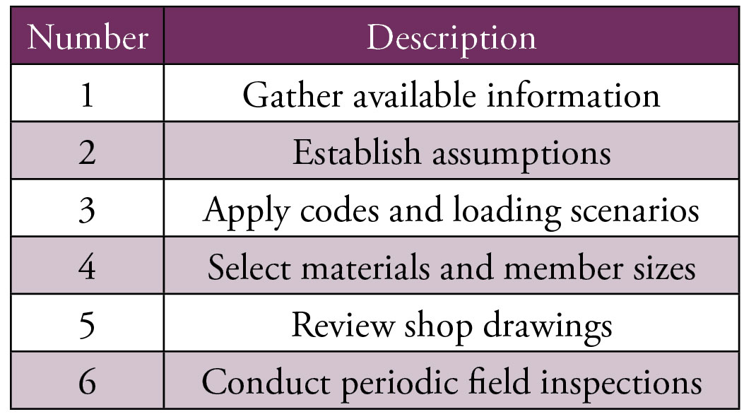
Table of Design Procedure.
These are the basic components over which the structural professional has some level of influence. When these steps are not completed or are hastily checked, problems may arise. The design process, or some iteration of it, applies not only to new construction but to evaluations of existing buildings as well. Proper assumptions, load applications, and inspections are still critical whenever structural review occurs.
Admittedly, an honest assessment reveals there are many other factors the designer cannot control or even predict. Structural professionals are sometimes forced to rely on: information they did not gather (others’ assumptions, site conditions, adjacent construction, water table, topography), processes outside their purview (material procurement, fabrication, delivery, site erection), as well as performance of trades (metallurgists, masons, steel and concrete contractors) and equipment (concrete vibrators, welders, nuclear density gauges) they do not oversee. These factors fall between process steps, in the gaps where problems can occur beyond the designer’s influence and direct oversight, and could lead to failures the structural professional would not have anticipated.
A collection of real-world project examples is compiled here to illustrate the importance of each step and demonstrate the risks within the process. Each case study highlights the results of taking shortcuts in the design procedure, the effects of outside factors occurring between steps, or a combination of both.
The Sounds of Silence
In Northern Michigan, a historic Catholic church stands at the center of a charming port town. Constructed in 1888, the church celebrates architectural influences from the mixed German and Irish heritage of the original parishioners. Highlighted among many striking features is the iconic 170-foot bell tower, which looms over the town, offering a welcoming beacon to those arriving by land or by water (Figure 1). For decades, the tower has been the centerpiece for cultural events in addition to being the original community center of worship. The community regularly gathered on the lawns around the steeple to attend free concert offerings from a 12-bell carillon housed within the tower. The idyllic tradition was recently cast into shadow when caretakers noted the existence of cracks, localized spalling, and general masonry disrepair. Concerns led parish leaders to adopt the understanding that the tower was falling apart. The presumed culprit? Vibrations and other dynamic forces from the motions of carillon bells. This justification led leadership to suspend concerts, eliminate all carillon usage, close the facility, and begin planning for the demolition of the historic building.
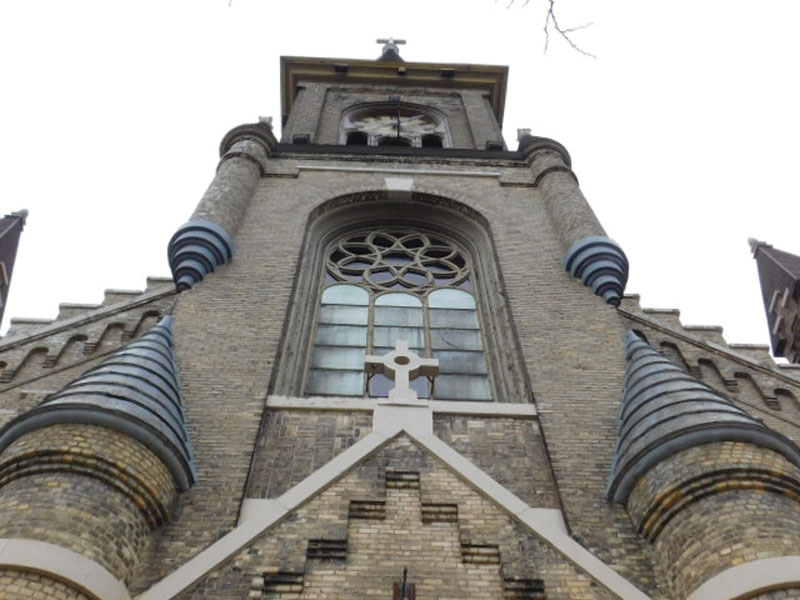
Figure 1. Front elevation view of 1888 church bell tower in Northern Michigan.
In hopes of saving the building, concerned staff and community members sought an independent technical opinion from a structural design professional. Grade-level exterior inspections revealed a series of cracks that existed in the exterior brick masonry at windows, doors, and near building corners. Presenting at areas of expected stress concentration throughout the building, these cracks were common in masonry of this vintage and not related solely to structural behaviors of the tower.
Significant gaps between the exterior masonry wall of the tower and the perpendicular flying buttresses of the adjacent side aisles were observed from windows of adjacent structures. Previous reports and assumptions asserted these gaps were specifically attributable to the usage of the carillon bells.
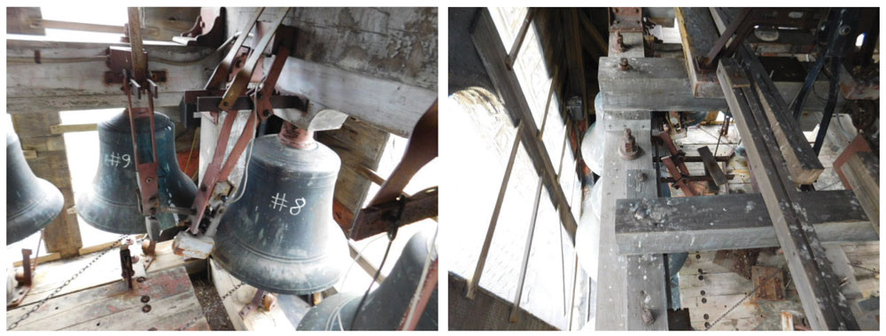
Figure 2. Left: View from the belfry where bells are observed to be permanently affixed and stationary. Right: View from the belfry revealing the bell support framing is structurally isolated from the tower
Implementing some respectful skepticism of established assumptions, the structural design professional climbed several flights of stairs and a few seldom-used ladders, which afforded admission to the rarely accessed carillon belfry. One notable feature became immediately apparent. The aged timber structure supporting the bells was structurally isolated. Over a century ago, the original designer astutely determined to keep the support of the carillon independent from the surrounding masonry facade. This was likely more challenging and less efficient for the builders, constructing one frame inside the other, but allowed for two completely isolated structures. A second critical observation was that the bells were permanently affixed in a stationary position, either by design or decades-old retrofitting. Instead of a bell rotating/swinging and sounding with an internal clapper, the ringing of each bell is activated by a side-mounted, electronically-activated hammer (Figure 2). Since they are stationary, the bells do not create any significant dynamic forces within the tower. Further, whatever minimal forces are initiated are not transferred to the masonry walls due to the as-designed structural isolation. Combined, these two realities painted the originally voiced concerns as potentially costly misconceptions.
Though this review occurred well beyond the original design timeline, the grasp of the current situation featured misunderstandings that led to significant problems. In this scenario, Step 1 of the “Design Procedure” was skipped or poorly executed and led to incorrect assumptions in Step 2. These assumptions grossly mischaracterized common masonry problems and led to misinformed decisions. The actual designer, of course, could not have been consulted, but grave consequences for a historic structure and the surrounding community were quickly unfolding.
As structural design professionals, it is critical to ask difficult questions, challenge the presented “facts,” and take extra steps to physically verify the actual conditions. Assuming the provided information is correct can be a mistake. Instead, skeptical review and verification are often appropriate.
Fortunately, in this case, the involvement of a structural professional furnished the church with a fact-based assessment and detailed explanations regarding typical exposure-related masonry cracking and separations due to long-term differential building movements. Armed with renewed insight, a phased masonry restoration program was initiated, the carillon restrictions lifted, and the community gathered around the spire once again to hear the bells ring.
Let It Snow
An indoor tennis facility on the western fringe of lower Michigan suffered snow-related damage during the unusually heavy winter of 2013-2014 (Figure 3). Averaging 76 inches of snow annually, the region recorded over 132 inches of snow and fewer warming/thawing cycles during this season, thereby leading to more significant overall snow accumulations. The pre-engineered structure was comprised of a fabric shell stretched over a series of structural steel arches, and was installed ten years prior. The shell reportedly exhibited visible deflections in several of the arches, causing the owners to close the facility and engage snow removal services. During the following spring, a structural engineering professional was engaged to document the extent of damage and provide a causation analysis.
Figure 3. Overall view of the fabric shell structure.
Field investigation and deflection measurements along the length of the frame segments found plastic deformation in six of the nine arches, ranging from less than 1⁄8 inch to as large as 5 inches. A review of available proprietary information, followed up with lengthy phone conversations with the pre-engineered system provider, revealed the designer, manufacturer, original installer, and the presumptive repair contractor were all the same entity. The manufacturer’s published deflection criteria provided more stringent deflection criteria than the governing codes. The technical representative explained the arches were not intended ever to hold snow, and the restrictive deflection criteria were intended to ensure snow accumulations on the fabric did not occur. That statement of assumption was both enlightening and concerning, considering the structure is within two miles of Lake Michigan, a historically documented heavy snow zone. The designer contended that the fabric surface, structure’s slope, and arch stiffness collectively prevent snow from accumulating. Actual events and structure performance suggested otherwise. Simply, snow accumulated on the roof caused expected deflection, which ironically allowed for additional accumulation and additional deflection (Figure 4).
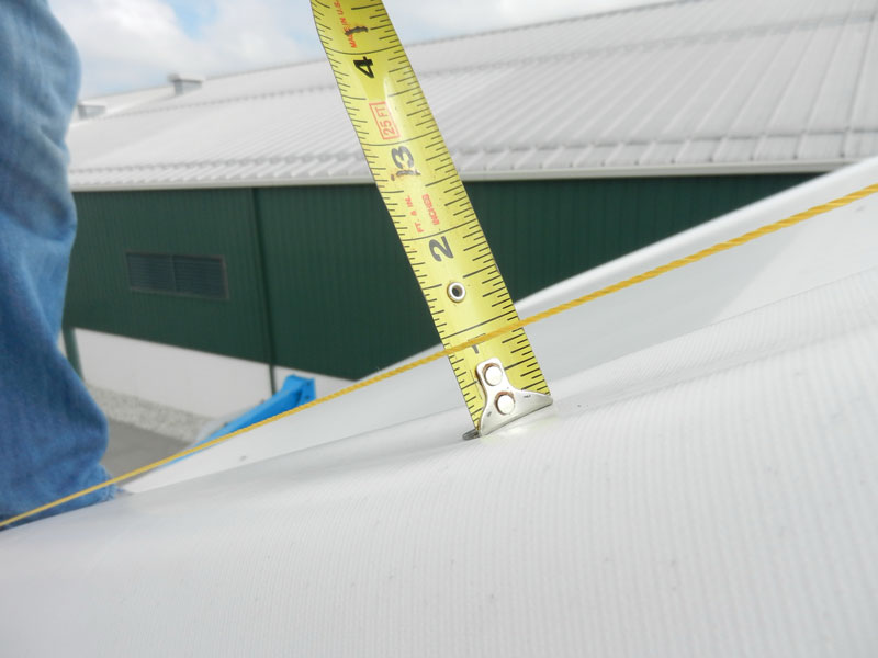
Figure 4. Steel deflection measurements collected along the length of the arch frames.
In this case, the designer applied incorrect assumptions in Step 2 of the “Design Procedure.” The proprietary design/manufacture/install model was generically applied in a location susceptible to snow loading contradicting the baseline assumptions. Anticipating the sloped segment of the arches would shed the snow before deflections led to improper application of the code-required loading in Step 3 of the “Design Procedure” and, eventually, poor material selections in Step 4. The flawed assumptions were exposed when snow fell and accumulated, liberally selected materials plastically deformed, and design parameters were unacceptably violated.
As structural design professionals, it is imperative to revisit assumptions regularly, especially those used repetitively. Different locations and situations always require renewed attention and verification of previous expectations. In the end, this site narrowly avoided a collapse and instead only suffered the arch deformations. All arches with permanent deflections out of manufacturer’s strict tolerances were replaced, operational heating recommendations were refined, and the building management implemented removal instructions for any future snow accumulations.
A Series of Unfortunate Events
A plastic molding and electrostatic plating company touting 50 years of manufacturing success and experience decided to support continued growth by adding a new manufacturing facility in Western Michigan. A 40-foot-tall high-bay structure comprised of steel columns, connecting girders, and panelized joist assemblies was selected, designed, and rapidly constructed to expedite the opening, usage, and profitability of the expanded facility. With over half of the structure and roof deck in place, a construction failure occurred. The collapse damaged two 50- x 60-foot bays of steel framing and one completed bay of roof joists and decking (Figure 5). During post-event interviews, the steel erector admirably accepted responsibility and provided insight on some contributing causes leading to the collapse.
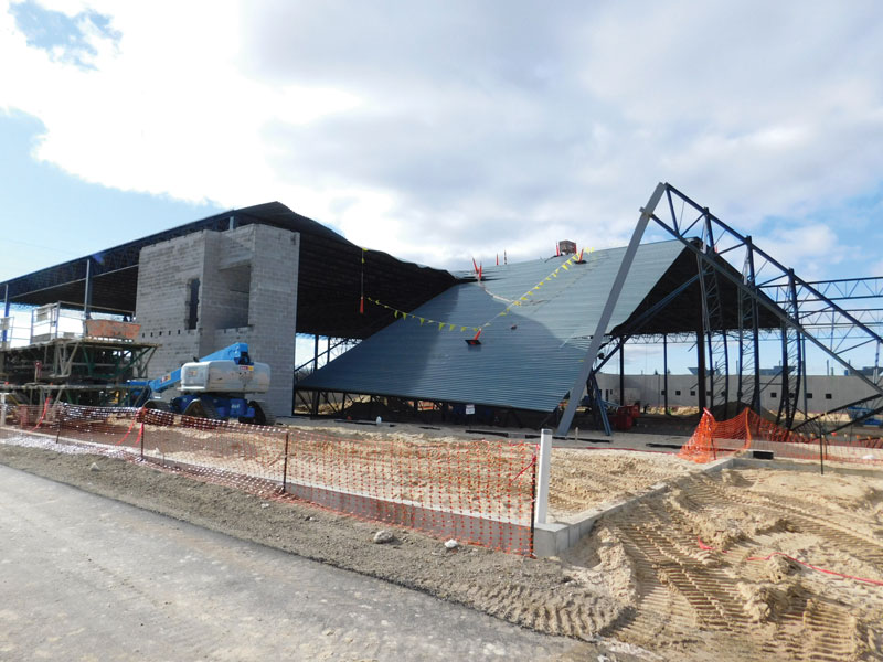
Figure 5. Partial view of framing and roof collapse.
After erecting two new columns and girders spanning from the existing frame to the new columns, the bay frame was not completed with a tie joist linking the two columns. Instead, since it was nearing evening and raining, the work was stopped early for the day, leaving the two girders and their end columns unbraced. Rain evolved into a storm with high winds causing the unbraced girders and columns to enter a dynamic cycle of out-of-plane displacements, eventually culminating in failure at the column baseplate connections. Felled columns pulled down their respective girders, which pulled additional columns and a progressive, multi-bay failure ensued. “All because of the rain,” as reported.
An additional detailed account of the events was found to be equally significant. The erector later shared that the tie joist was not even on-site with the other frame components. The delivery truck with that specific component had suffered a flat tire, delaying the arrival and leaving the erection sequence disrupted. In their haste to stay on schedule, the crew elected to move forward, planning on a late arrival and a last-minute installation of the tie joist. The rain soured that plan.
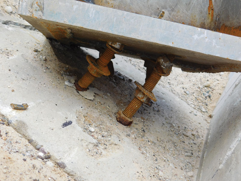
Figure 6. Close-up view of anchor bolt washers and nuts that pulled through oversized baseplate holes.
Closer inspections of the debris field found oversized double holes in the column baseplates and cupped round washers. Some washers and nuts had completely pulled through their baseplates (Figure 6). Other anchor bolt assemblies where columns were not yet placed were found with brand new square plate washers installed and corroded round washers discarded nearby. Clearly, material selection and field implementation had suffered and contributed to the event. A detailed review of the joists revealed numerous failed welds at the bearing seat angles as well as misplaced, oversized holes. Poor weld quality allowed shearing failures between joist webbing and the seat angle (Figure 7), leaving the entire seat angle perched on top of the column. Fabrication of the joists, particularly the quality of the welds, was now in question as well.
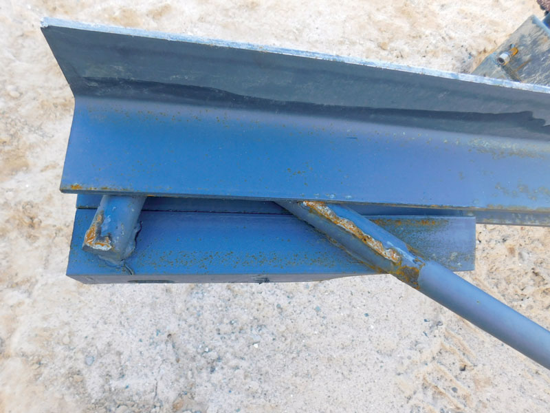
Figure 7. Close-up view of joist seat, which has sheared off at suspect quality weld locations.
This case exemplifies the susceptibility of the gaps between steps in the design process. An extensive series of fabrication, delivery, installation, and erection problems compounded to cause a large-scale construction failure. Specifically, the flat tire impacted material delivery, which disrupted the steel erection sequence, which was exacerbated by a rainstorm. All of these occurred somewhere well after Step 5 and before Step 6 and were outside the direct supervision and control of the designer. Step 4 may have been poorly executed by the designer, sizing washers that were too thin and/or too small. Oversized holes of poor workmanship, coupled with poor erection decisions, created a susceptible condition which exposed the washer issue and led to pull-through failures. In Step 5, the designer checked the shop drawing and expected a competent weld, and then reviewed the erection plan and expected the sequence to be completed with all the parts. Actions of others between the design steps were the letdown. Nearly all of these linked factors occurred outside of the purview of the structural design professional and amassed to create a significant failure.
Each of the steps of the design process is critical and requires refined attention on every project. Missing or poorly executing any step can lead to failures, property damage, and possibly loss of life. Disruptive factors or dismissive postures can lead to misunderstanding, misapplications, and improper assumptions. Even a flawless design execution is susceptible to hazards of unexpected complications, many outside the designer’s control. Designers must remain engaged, ask additional questions, be respectfully skeptical, and challenge both assumptions and provided information. Whenever possible, designers must regularly verify that expectations are met in the shop and the field. While these intentional engagements may require extra effort and may be perceived as finicky, the added value of catching and correcting potential mishaps provides a high return on investment. The structural design industry should embrace and reinforce the vision that additional engagement benefits all parties by reducing risks of failure, property damage, and the general occurrence of unfortunate events.■