Challenges in Repairing a Severely Corroded Rooftop Cooling Tower Support Structure
Repair of corroded steel supports caused by a leaking cooling tower on an aging building’s roof can be incredibly challenging for structural engineers. A case study of rooftop cooling tower support structure repairs highlights common obstacles and solutions for these rising problems.
Deteriorated steel structures are often repaired by reinforcing the existing elements with additional steel. In cases of severe deterioration, replacement may become more practical than reinforcement. Full or partial replacement of the structural support requires unloading the support by temporarily shoring its load. This may seem a straightforward operation, but it can quickly become challenging when it involves shoring a 350,000-pound cooling tower on the roof of a high-rise designed for a modest 20 pounds-per-square-foot live load. Although it may be tempting to postpone these complicated repairs, the cooling system’s failure could make the building uninhabitable – or worse, if the support structure collapses onto the fully-occupied office space.
Case Study
The case study involves a cooling tower on top of a 46-story commercial building constructed in 1975. The building was well maintained, but care of the rooftop structure was deferred. In 2018, Engineering Diagnostics was engaged to design repairs for corrosion of the cooling tower support structure discovered after a change of building maintenance staff.
The cooling tower serves over one million square feet of office space in a hot and humid climate, which means that it had to remain operational during the repairs. The approximately 2,400-square-foot cooling tower is a timber and fiberglass structure supported by steel wide flange beams and girders that bear on base isolators. Some of the steel shapes used in 1975 are no longer produced, requiring research into the American Institute of Steel Construction’s (AISC) archives of “historic” shapes. The base isolator springs dampen the cooling tower’s mechanical vibration before transferring the load to concrete pedestals that support the tower on the roof.
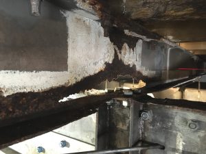
The existing structure’s assessment revealed that the steel girders had experienced up to 50% section loss in some of the webs and flanges. In some locations, personnel could poke their fingers through the web (Figure 1). The most severe corrosion was observed directly over a central concrete pedestal. Each of the 12 concrete pedestals was built with four encased steel pipes, which had also been damaged by corrosion.
The preliminary repair strategy consisted of (1) partial replacement of the corroded girder, (2) reinforcement of less corroded beams with angles and stiffeners, and (3) patching spalled concrete on the pedestals. Temporary shoring was installed while Engineering Diagnostics worked on the development of the final repairs and shoring plans.
Design Challenges
At first glance, the solution for reduced steel cross-section is simple: add more steel. The challenges posed by the cooling tower’s location, its significant weight, and minimal roof capacity required several iterations to the repair strategy. The original design drawings were illegible; therefore, the as-built construction had to be visually confirmed.
The building maintenance staff reported the tower was operating with 60% more basin water than specified in the original design documents. The weight of water was a particular concern for the performance of the base isolator springs and the temporary shoring.
The steel support structure had been wetted by rain and continual leakage from the cooling tower basin. In addition to steel corrosion, the base isolator springs had bottomed out from age and overload. This resulted in vibration-induced spalling in the concrete pedestals.
The corrosion across the web and flanges of some sections was so significant that it would be necessary to cut out the deteriorated length and to splice in new pieces. Adding steel plate reinforcing was also considered; however, several areas exhibited insufficient “healthy” steel for suitable welding or composite shear flow through the beam. Further, the repair steel would have covered most of the existing steel, impeding the ability to monitor for future corrosion.
Substitution of the damaged beam section appeared more practical. Shoring would need to redirect the cooling tower loads while the corroded steel was cut out, and a new section was spliced in. Unloading the members nearest to one pedestal by shoring would result in a change in the loading of the other pedestals. The roof framing was analyzed as a system to understand the unintended effects of shoring.
Since the floor below was occupied, extending the shoring to lower floors was not a viable option. Congestion of pipes and air ducts below the tower further constrained the shoring options. RISA-3D was used to develop a detailed three-dimensional model of the cooling tower support structure and roof framing. The model was used to identify the shore positions such that the members of concern were completely unloaded, and the roof framing members and connections would not experience a surcharge. Shoring beams were placed below the cooling tower and on the roof deck to transfer the loads directly to a strong roof beam rather than the slab spans.
Construction Challenges
The first stage was to remove the rust, and that is when construction obstacles began. A sandblasting compressor could not be brought to the roof, so the rust had to be removed by grinding, which extended the cleaning time. The roof hoist’s elevator dimensions and capacity limited the weight, transportation, and assembly of tools, shoring, temporary beams, and repair materials. Steel cleaning near the building air-intakes required careful protection to ensure tenant safety. The cleaning process revealed additional steel damage and section loss, which necessitated additional iterations of the repair design.
The structural evaluation of the roof framing indicated that only portions of the cooling tower could be shored at one time to avoid overstressing the framing with concentrated shoring loads. Partial shoring increased the risk of differential movement and subsequent seam leaks in the basin’s plywood decking. The cooling water leakage risk applied to potential machinery damage, water infiltration to the commercial space below, and continued corrosion.
The cooling tower basin consists of plywood sheets supported on 4-inch square (4×4) wood beams supported by the steel beams and girders. Unloading the steel beams required using post shores to lift the wood beams just enough to remove the corroded steel beams while minimizing the differential movement in any zone. It was essential to schedule hold points during the shoring process to monitor for new leaks.
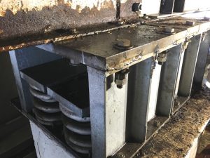
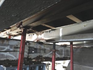
Before the shoring process began, the as-built construction of the roof framing was verified by accessing the roof’s underside. Temporary lateral braces were installed at shoring points and at locations where bracing members were disconnected. Although the lifting process was intended to unload the steel beams, it would also decompress the isolator springs supporting them. This decompression would push the beams upwards and prevent the intended clearance gap between the steel beams and the cooling tower. The base isolator’s top bearing plate was temporarily welded to lock its position (Figure 2). Shoring beams placed on each side of the repair lifted the wood beams from the top of the subject steel (Figure 3). A laser level was used to monitor the displacement progress.
The post shores operate based on a screw jack system. Once the shores were each snug-tight against the structure, the lifting team would advance all shores in a row by half a turn, alternating between rows. Lifting the wood 3⁄16 inch proved adequate to install the new steel beam sections.
After stabilizing the shores, the contractor cut out the deteriorated beam section, and a new piece was spliced with welded full-moment connections. The placement of welded splices was designed around the wood beam locations with appropriate fire watches. Bent splice plates were used to join the new and old steel. These plate bends were necessary because of the mismatch between the historic steel shape heights and the new steel shapes.
The remaining beams and girders were repaired by reinforcing with bolted composite steel angles at the flanges and adding web stiffeners. The cooling tower did not need to be lifted for the reinforcing repairs because the beams were not replaced. Shoring was used to unload the steel sufficiently to allow the reinforcing to share the load of the tower, as opposed to carrying incremental additional load.
Because of the wet environment, it was essential to prevent water from being trapped between the new and old steel. The perimeter of the steel joints was sealed, and the structure was epoxy coated to ensure the durability of the repairs.
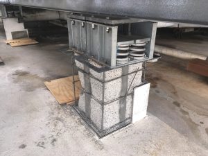
The concrete pedestals also revealed more significant distress than initially evident. The contractor removed loose concrete up to 8 inches deep, revealing encased steel pipes (Figure 4). Ultrasonic testing was used to confirm that the pipe thickness was adequate to remain in place. The steel was cleaned, new mild steel reinforcement was installed, and concrete patching was placed.
Conclusions and Recommendations
What initially appeared as a straightforward steel reinforcing project revealed several interesting challenges during the structural assessment and the subsequent repairs. This project’s successful execution was made possible by timely and clear communication between the property management team, contractors, and engineers.
The repair of rooftop cooling tower support structures can be risky due to unique challenges. In the case study, these included building occupancy, the cooling tower assembly’s sensitivity to displacement, large supported loads, low roof capacity, and lack of original design documentation (typical for older buildings). Consistent monitoring of the process by the engineers was critical to ensure that the design intent was met, especially in rehearsing the shoring plan. This project had easy access to visual monitoring of the health of the structure. In the end, monitoring and maintenance is the best course of action to prevent and mitigate the need for such repairs and preserve the integrity of older buildings.■


