
Unreinforced CMU Wall with Diagonal Step Crack
Modern CMU construction almost always requires the installation of vertical reinforcement in the grouted cells of the CMU. However, addressing structural issues associated with unreinforced CMU construction prevalent prior to the 1990s can be daunting. In the author’s experience, today’s engineers do not know how to deal with, or adequately investigate, diagonal cracks in unreinforced CMU walls. The discovery of such cracks quite frequently leads to the unjustified conclusion that this type of distress affects the capacity of the wall to resist lateral wind pressure loads. This article investigates the lateral capacity of an ungrouted and unreinforced CMU wall affected by a diagonal step (stair step) crack. The analysis demonstrates why a diagonal corner crack should not be qualified as structural damage.
Known Data
A 54-foot by 24-foot structure with 8-inch-thick ungrouted CMU walls is located in an area with wind exposure “B” and an ultimate wind speed of 140 mph. The wall is 8 feet 8 inches high. The roof, which overhangs the wall by 2 feet, is sloped 3:12 and is supported by roof trusses spaced 2 feet apart. The roof dead load is 10 psf and wall self-weight is 42 psf (normal weight of an ungrouted CMU wall). A crack runs diagonally from the top of the wall at the corner down to the base. The analysis is per ASCE 7-10, Minimum Design Loads for Buildings and Other Structures, using Components and Cladding pressures.
Solution
Considering the slope of the crack, the horizontal projection of the crack is equal to the wall height of 8.67 feet. The 2.4-foot-wide High-Pressure Zone at the corner is reinforced. Therefore, only the portion of the crack in the unreinforced Normal-Pressure Zone is considered here.
Wind pressure loads are based on wind tributary area for components and cladding:
- Roof Ultimate wind pressure: p = -35.3 psf
- Additional wind pressure [2-foot overhang]: p = -65.7 psf
- Wall Ultimate wind pressure: p = -36.2 psf
- Critical Wind Load Combination, LC 7, ASCE 7-10, Chapter 2.4 (ASD)
LC 7 = 0.6DL + 0.6W
Roof load at roof truss to wall attachment:
Ax top = -443 lbs tension per 2 feet of wall length, uplift at top of the wall
The most critical section is in the middle of the wall, where the wind moment is the largest.
For the load diagram, see Figure 1.
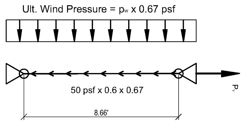
Figure 1. Wall 8-inch strip load diagram.
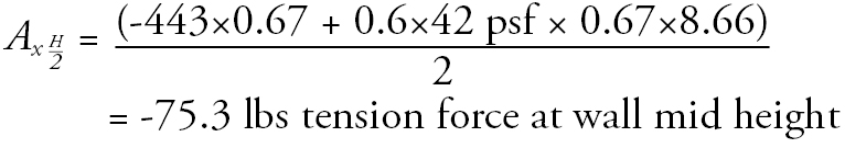
Axial load at the middle of the wall (per 8 inches of vertical strip of wall) is:
Pv = Ax top = 443 lbs/every 2 feet
pw = 36.2 psf (Ultimate wind pressure)
= 136 lb-ft per 8-inch horizontal crack or 1,637 lb-in per 8 inches
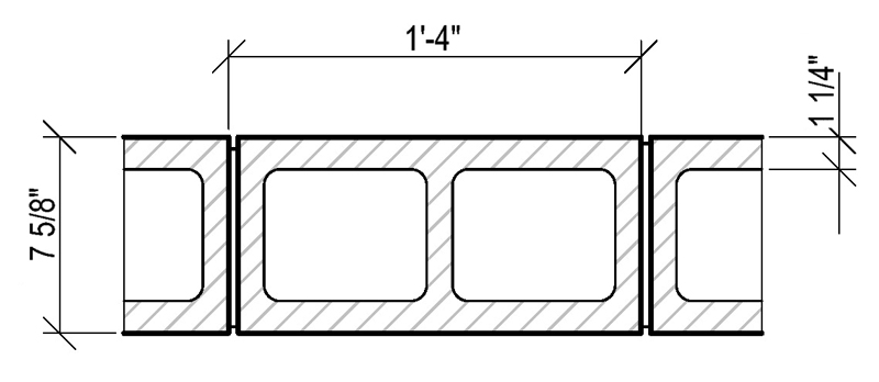
Figure 2. CMU block geometry.
- Tension Stress: Uplift versus Gravity (Figure 2)
Note: stresses in the wall are calculated for an 8-inch vertical strip of the wall.
![]()
- Tensile stress due to flexure caused by wind, considering un-cracked section:
- Total tension stress, assuming uncracked section:
-fa = -(25.70+2.60) = -28.30 psi
- Modulus of rupture, fr, for masonry elements subjected to out-of-plane bending shall be in accordance with the values in Table 9.1.9.2 of ACI 530-13, Building Code Requirements and Specification for Masonry Structures and Companion Commentaries, for Portland cement type N, normal to bed joints for ungrouted CMU: fr = 64 psi
This value incorporates a 33% increase in the stress allowed for wind load. This value applies only to the flexural tensile stress developed between the masonry units, mortar, and grout. ASCE 7-10, Chapter 2.4.1, Exceptions, states: “Increase in allowable stress shall not be used with the loads or load combinations given in this standard unless it can be demonstrated that such an increase is justified by structural behavior caused by rate or duration of load.”
Unmodified Modulus of Rupture becomes:
The analysis must also include redistributed stresses from the cracked section (8-inch-wide horizontal crack) along the uncracked portions of the Effective Resisting Width of the wall panel.
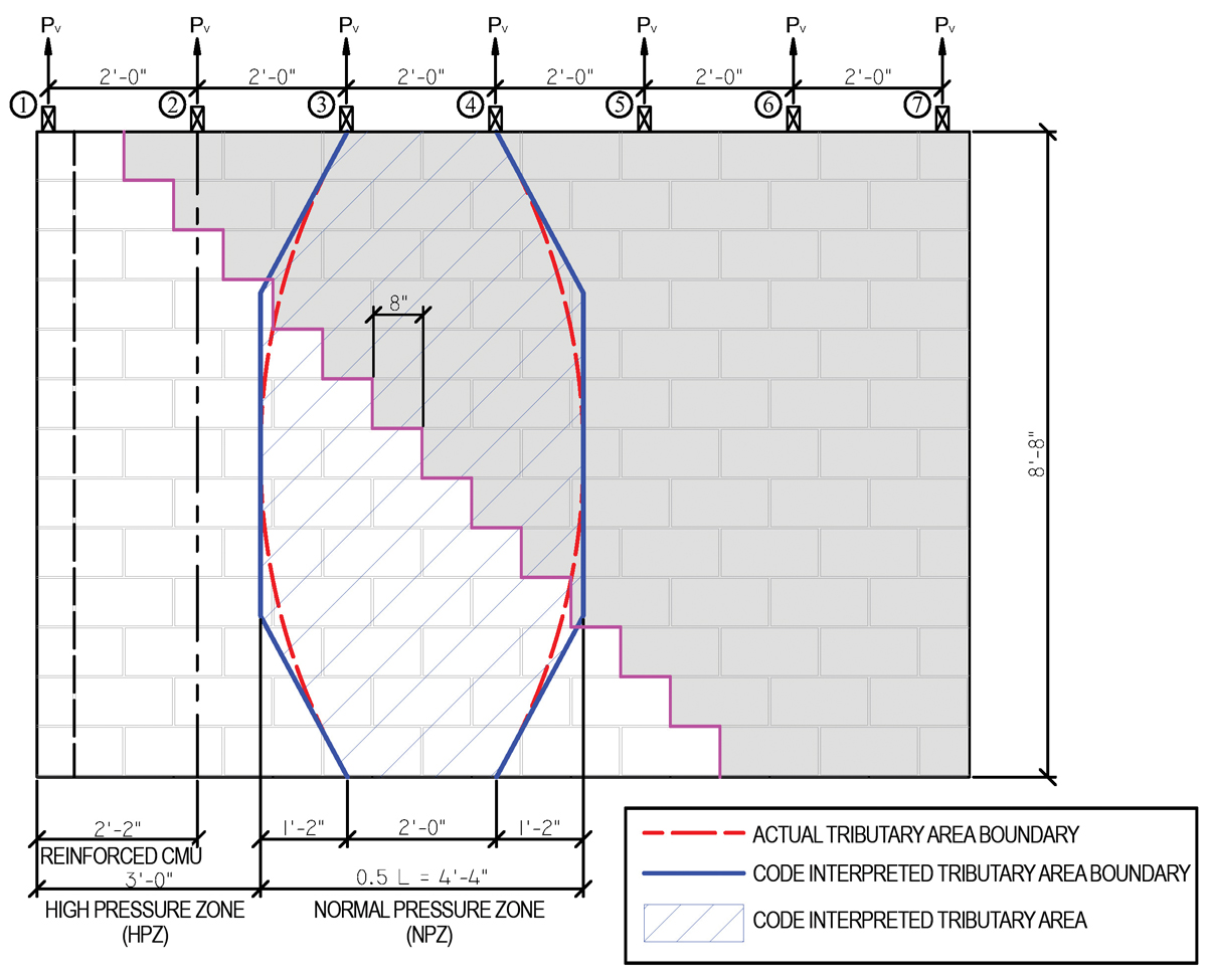
Figure 3. Effective resistance width of slab for distributable concentrated load.
Force redistribution theory (Figure 3), based on spring stiffness along the span of the wide plate, was first introduced for the analysis of flat plates with distributable and non-distributable loads by S. Timoshenko in the Theory of Plates and Shells. It was first successfully utilized for the design of Hollow Core Slabs (PCI Manual for Design of Hollow Core Slabs). The same analogy can be utilized for the analysis of CMU walls.
The wide plate is viewed as a trampoline having different spring values along the span. The spring is defined by k = P/δ
where,
P = 1 kip – a unit force placed anywhere along the span of the 1-foot-wide strip of the plate
δ – is a deflection of the 1-foot plate strip under the unit load
Since a stiffer spring along the plate span narrows the “effective resistance width,” a softer spring will widen the zone of the distributable load redistribution. Figure 3 shows the boundaries of the distributable width utilized for the distribution of the load applied to the strip with a plastic hinge (a short horizontal crack in the wall strip).
However, before confirming the redistribution force model, check the clamping action from the vertical cantilever action created by the shaded area of the wall above the diagonal crack (shown by the magenta line in Figure 3).
Limit State I – Cantilever action of the wall above the crack (Figure 3):
The shaded portion of the wall is acting as a vertical cantilever with clamping force investigated at locations 3 and 4.
- Location 3 is 5 blocks high (5×8 = 40 inches tall)
Uplift moment, Mup3 = 443×(24) = 10,632 lb-in
Downward moment from self-weight of the CMU above the crack Msw3 = 39,765 lb-in
The resisting downward moment, Msw3 = 39,765 lb-in > Uplift moment of Mup3 = 10,632 lb-in
- Location 4 is 8 blocks high (8×8 = 64 inches tall)
Uplift moment, Mup4 = 443×(48+24) = 31,896 lb-in
Downward moment from self-weight of the CMU above the crack Msw4 = 173,525 lb-in
The resisting downward moment, Msw4 = 173,525 lb-in > Uplift moment of Mup4 = 31,896 lb-in
Limit State II – The shear stress at critical locations:
Allowable shear stress of the CMU block (ACI 530-13, 8.2.6.2) is
Fv = 37 psi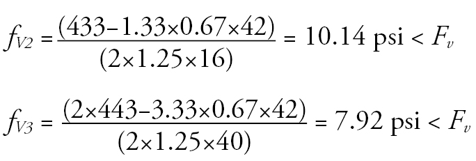
The uplift force from the wind acting on the roof does not affect the assumption of effective resistance width shown in Figure 3.
Clamping action, created by a gravity load of the portion of the wall above the diagonal crack at the two critical locations, allows for the distribution of the distributable load within the effective distributable width.
Limit State III – Effect of the partial limited hinge created by a hairline diagonal step crack:
The out-of-plan flexure resistance mechanism activated within the hairline crack is shown in Figure 4. If the cantilever above the crack is not sheared by torsional force induced by flexure, the horizontal crack forms a partial plastic hinge restrained by the wall gravity and CMU shell shear capacity.
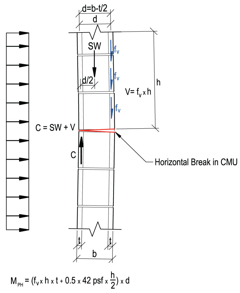
Figure 4. Partial plastic-hinge resistance.
Partial Plastic-Hinge capacity of the cracked CMU
At wall mid-height:
![]()
At ¾ wall-height:
![]()
Note: Contribution from the roof DL was conservatively neglected.
The allowable flexural capacity of the unconfined wall under simple beam flexure:
Mall = fr ×1.25×12×(7.625−1.25) = 48×1.25×12×6.375 = 4,590 lb-in/ft (based on mortar rupture)
Mall = ft ×1.25×12×(7.625−1.25) = 25×1.25×12×6.375 = 2,390 lb-in/ft (based on allowable tensile stress of hollow ungrouted CMU with type ‘N’ mortar cement)
Both partial hinges exceed the flexural capacity of the unconfined unreinforced CMU wall.
It was analytically proven that a hairline crack forming a partial plastic hinge in the unreinforced wall with a diagonal crack does not degrade the wall’s flexural capacity.
Taking into consideration the statement above, additional distributable stress is taken by the uncracked portion of the effective resistance width of the CMU wall (Figure 3).
Effective Resisting width at mid-height of the wall is equal to:
0.5H = 0.5×8.66 = 4.33 feet or 52 inches
Additional distributable stress
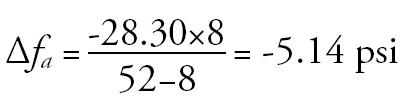
Where 27.84 psi is total tension stress assuming uncracked section.
Adding that additional distributable stress to the stress in the uncracked section of the effective resistance width results in:
fa distr = -(28.30+5.14) = 33.44 psi < fr = 48 psi
Although analysis for three-quarter wall-height could be provided, net tensile stress at that location is smaller than at the wall mid-height.
Therefore, it was proven that the adjacent uncracked cells within the effective resisting width with a diagonal crack could effectively resist the wind load without endangering the stability of the building.
Conclusion
Numerical analysis proves that a hairline diagonal crack in the ungrouted CMU walls, in the absence of severe foundation damage, should be categorized as “local distress” rather than “structural damage”.■