
Designing Stanford University’s Escondido Village Graduate Residences
Given the high cost of rent in the surrounding community and a campus housing capacity of 55 percent of its graduate student population, Stanford University needed to increase its graduate student housing. The goal was to not only provide better housing options for its current students but also continue to attract the best students from around the world. The Escondido Village Graduate Residences (EVGR) at Stanford University adds more than 1,300 units and 2,400 beds, increasing Stanford’s on-campus graduate housing capacity to 75 percent of its graduate student population.
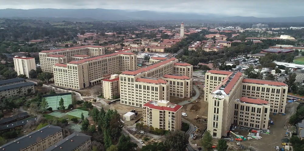
The Escondido Village Graduate Residences (EVGR) at Stanford University.
The project primarily consists of four new residential buildings, a collection of six-, eight-, and ten-story towers, totaling more than 1,800,000 square feet. Also included is a new, three-story pavilion building, providing support amenities including a restaurant, brewery, and multipurpose room.
Projects of this magnitude and complexity often present the team with various design and construction challenges, and EVGR was no exception. The existing Escondido Village is the largest graduate community at Stanford and, because it is an active campus, the design-build team for the new EVGR was charged with delivering the project as quickly and with minimal disruption and negative impact on the surrounding neighbors as possible. These parameters drove the team to select a prefabricated, precast concrete system, which allows for the majority of building construction to be fabricated off-site within a controlled shop environment, thereby reducing noise, congestion, and field labor. John A. Martin & Associates, Inc. (JAMA) worked in close partnership with Clark Pacific, the precast concrete subcontractor, to develop and design the all-precast concrete structural system for EVGR.
Since the project is in a high seismic region, earthquake resistance was an essential objective of the structural design. Instead of a code-prescriptive design approach, Stanford University required a performance-based approach to design the lateral system. The residential buildings are designed to achieve Class 2 seismic performance following Stanford’s Seismic Engineering Guidelines, using the criteria outlined in the ASCE 41-13 standard, Seismic Evaluation and Retrofit of Existing Buildings, to evaluate the components. Class 2 buildings provide enhanced seismic performance and are classified as facilities critical to the operation of the University. In terms of structural performance, the Class 2 designation implies limited damage (corresponding with Damage Control performance in ASCE 41) at the Design Response Spectra (DRS), or BSE-1N equivalent seismic hazard, and enhanced safety (corresponding with Life Safety performance in ASCE 41) at the Maximum Considered Earthquake Spectra (MCER), or BSE-2N equivalent seismic hazard. BSE-1N and BSE-2N have return periods of 475 years and 2475 years, respectively.
Gravity Framing System
The building height at the six-, eight-, and ten-story towers is 72 feet, 94 feet, and 116 feet, respectively. The typical floor-to-floor height is 11 feet, with a 17-foot story height on the ground floor. The gravity framing system consists of double tee precast floor panels with 4-inch-thick flanges and 12-inch-wide by 15-inch-deep ribbed sections. The floor panels are approximately 10.75 feet wide and span up to 35 feet parallel to the longitudinal direction of each building and span between precast moment frames that extend the full width of the building. The three-bay transverse moment frames supporting the floor panels are comprised of 18-inch-wide by 36- or 42-inch-deep columns and 24-inch-wide by 25- to 44-inch-deep moment frame beams.
Foundation System
The buildings are supported on continuous spread footings under each moment frame, sized to support the service loads using site-specific soil properties. The footings were designed using a capacity-based approach. That is, the continuous footings were designed to resist the maximum force that the moment frame columns can transmit to the footings. The thicknesses of the continuous footings were governed by the resulting shear forces induced by the expected moment capacities of the moment frame columns in combination with the shear forces due to the gravity loads. Rebar congestion was reduced by utilizing 80 ksi reinforcement and by eliminating stirrups in the foundations. This was accomplished by thickening the footings so that the concrete section alone could resist the shear forces. The tradeoff for reducing the amount of rebar in the foundations was the requirement of larger footings. However, eliminating the labor-intensive work associated with configuring and installing numerous stirrups helped accelerate the project schedule, and offset the cost of the additional concrete and excavation for the larger footings.

Exterior longitudinal moment frame.
Lateral Framing System
To achieve a Class 2 seismic performance, each residential building is divided into four or five seismically separated structures. Therefore, the “four” residential buildings are actually seventeen individual buildings. This improved the seismic performance by avoiding horizontal and vertical structural irregularities such as torsional irregularities and reentrant corners. It also simplified the lateral design by standardizing the design of multiple buildings that have similar configurations. In turn, standardizing the building designs helped optimize the design of the precast panels, minimizing the number of custom forms required for the project.
The precast panels that comprise the special moment frame elements consist of a continuous beam and discrete column panels in the transverse direction of the buildings. Longitudinal moment frames consist of two or three columns joined by a top and bottom beam. Column continuity is achieved by utilizing grouted couplers and corrugated rebar sleeves. The transverse beams used low amounts of post-tensioning reinforcement to prevent cracking during shipping and were formed with pre-coordinated MEP penetrations. The seismic performance evaluation was performed simultaneously with the frame design, driving optimization of the rebar design to maximize ductility through symmetric top and bottom flexural reinforcement, and by sizing beams to strategically align stiffness and strength at locations of high stress.
The use of precast concrete offered advantages to achieving Class 2 seismic performance. First, Clark Pacific’s preference for repetitive member design meant that every frame could be a moment frame, resulting in a highly redundant system without incurring additional costs. Second, individual panel designs were replicated across different stories and building segments. This approach led to panel designs optimized for a worst-case location and provided residual strength in other areas. Finally, the architectural expression of the buildings was integrated directly onto the concrete panels in the precast forms, eliminating the need to detail additional façade elements.
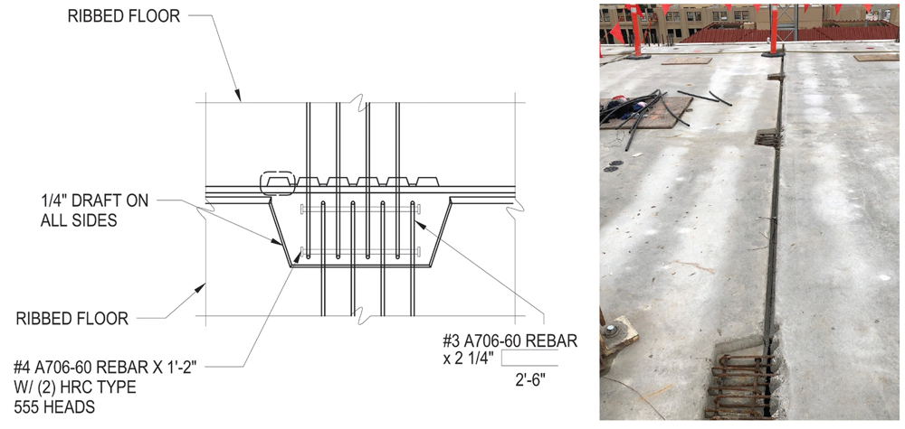
Diaphragm shear connection detail.
A significant source of innovation on this project was the design of an un-topped precast diaphragm. Precast floor-plank to floor-plank-edge connections have historically performed poorly in seismic events, creating a dependence on cast-in-place topping slabs for diaphragm action, which in turn becomes the limiting factor for construction speed. For this project, the design team reimagined the precast shear transfer connection as an extension of monolithic concrete behavior instead of using the typical approach of embedded steel elements welded together across planks. The precast planks were connected to each other and to the surrounding frames using interlaced rebar hairpins that lapped each other and hooked around a lacer bar running parallel to the plank edges, drawing from concepts used in precast bridge design. These connections were arranged in a continuous pattern at the plank-to-beam interface and formed at discrete locations between floor planks. The joints were then filled with grout to create a connection that mimics cast-in-place concrete behavior.
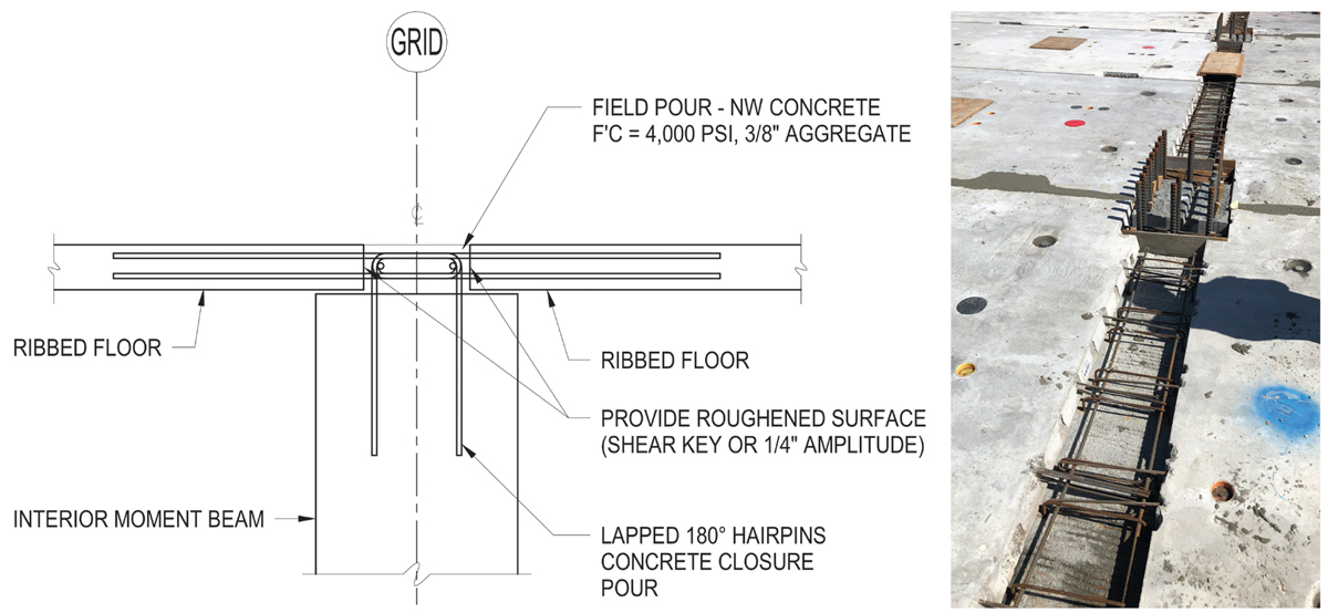
Diaphragm connection to transverse moment frame detail.
Diaphragm chord elements for resisting flexural demands were created with a similar connection of lapping rebar hairpins that develop the strength of the chord bars within the planks. At a handful of particularly tricky locations with high transfer demands, partially stressed post-tensioned strands were anchored within the floor planks along the chord length to provide a supplemental source of strength. The post-tensioning provides additional elastic strength, and the residual unstressed capacity activates when the mild chord reinforcing yields and dissipates energy.
Construction
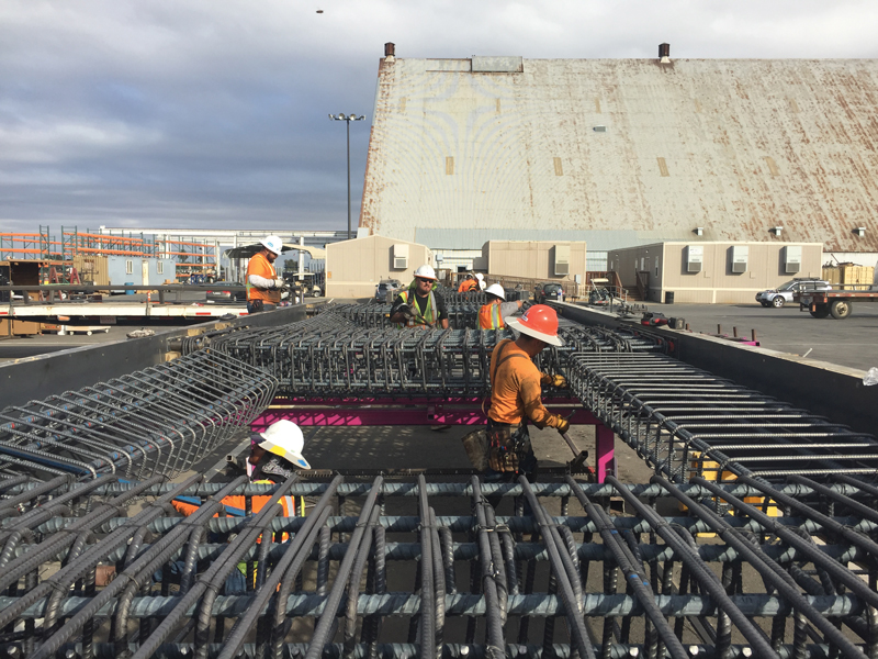
Moment frame panel production.
There are approximately 14,700 prefabricated precast panels that make up the EVGR residential buildings. By working closely with Clark Pacific throughout the design development and construction documentation phases of the project, the designers were able to optimize the designs of the precast panels and minimize the number of forms needed for fabrication. The sharing of BIM models between JAMA and Clark Pacific was essential to the project workflow, as the design team was able to convert Clark Pacific’s Tekla model to Revit smoothly. Sharing models during design ensured that the shop drawing submittals were consistent with the construction documents; in reviewing all the 14,700 panel shop drawings, there were only a handful of corrections noted. The efficient submittal review process enabled the panels to be fabricated and transported to the site in a timely manner. Ultimately, the four residential buildings were installed in only 11 months, realizing an estimated time savings of 30% to 40% when compared to conventional cast in place construction.
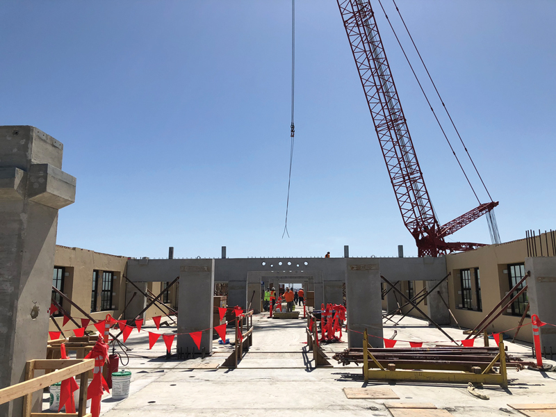
Transverse moment frame erection.
The prefabricated precast concrete solution developed by the design-build team addressed the combination of the site’s logistical challenges and building performance requirements while reducing the construction schedule and minimizing disruption to the campus. Furthermore, leveraging the efficiencies inherent with prefabrication and precast concrete resulted in resilient structural design. EVGR is scheduled to welcome its first set of students this fall at the start of the new school year.■