
Although commonly used throughout the building industry, the term “mass timber “will be included in the International Building Code (IBC) for the first time in the 2021 Edition. Mass timber will be defined as structural elements of Type IV construction primarily of solid, built-up, panelized, or engineered wood products that meet minimum cross-section dimensions of Type IV construction. Cross-laminated Timber, or CLT, is one of the major wood products used in mass timber construction that has started to gain traction in the North American building sector as a viable major building material due to its structural properties, sustainability, and inherent fire-resistance.
CLT is a prefabricated engineered wood product consisting of not less than three layers of solid-sawn lumber or structural composite lumber, where the adjacent layers are cross-oriented perpendicularly and bonded with structural adhesive to form a solid wood element. Finished panels are typically 2 to 10 feet wide, with lengths up to 60 feet and thickness up to 20 inches. CLT is commonly used for long spans in walls, floors, and roofs. With its inclusion in the National Design Specification® (NDS®) for Wood Construction and the IBC, the material is becoming more commonly used. However, design examples on the use of this new material remain limited. This article provides information on CLT as a material, its production, and uses, and provides a design example for a CLT wall application.
Historical Background and Use
CLT was first introduced in Europe in the 1990s and has grown in popularity in the years since, with over 500 CLT buildings in England alone. Even before being adopted in U.S. codes and standards, CLT was used in buildings such as Long Hall in Whitefish, Montana (the first CLT commercial building), Franklin Elementary School in Franklin, West Virginia (the first CLT school building), and several more. The WoodWorks website reports that there are currently over 350 CLT projects that are either in construction/built or in design, and over 700 projects using other mass timber products throughout the U.S. The Table provides a sampling of projects:
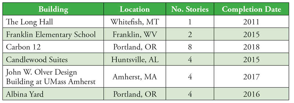
Table of U.S. CLT building examples.
In the 2015 and 2018 IBC, CLT is limited in use to low and midrise buildings, mainly of Type III, IV, and V Construction, and may not be used in tall buildings.
Codes and Standards
CLT was first standardized in the U.S. in the 2015 NDS and adopted in the 2015 IBC. The production standard in the 2015 and 2018 IBC for CLT is ANSI/APA PRG 320-11 and ANSI/APA PRG 320-17, respectively. However, if designers are considering using CLT for “tall buildings,” ANSI/APA PRG 320-18 should be used due to a change in the adhesive requirements. PRG 320 provides design values for specific grades of CLT, geometric properties, and adhesive requirements that manufacturers must meet. Structural reference design values for CLT should be obtained from the CLT manufacturer’s literature or code evaluation reports.
Although CLT may be used for roof, floor, or wall applications, there are limited design examples available. A conceptual CLT wall design example for axial loads and combined out-of-plane and axial loads is shown below. (Note that the loads are not factored per ASCE 7;
the example is shown for proof of concept rather than a complete design example.)
Example – Combined Bending and Axial Loads
For this exercise, a CLT wall subjected to axial compression and out-of-plane wind load (perpendicular to the face of the wall) is investigated. The design loads and parameters are:
Live load = 15,000 plf
Dead load (including estimated self-weight) = 7,500 plf
Wind load = 25 psf
Wall height = L = 10 ft = 120 in
The wall will be designed on a unit width basis, so all loads will be calculated based on a 1-foot- wide section. The loads per unit width:
Axial loads
Live load = Plive = 15,000 lbs
Dead load = Pdead = 7,500 lbs
Total load = Ptotal = Plive + Pdead = 22,500 lbs
Bending loads
Wind load = wwind = 25 plf
The initial design will consist of a 3-ply CLT panel made from
1 3⁄8-inch × 3 1⁄2-inch lumber boards (CLT thickness of 4 1⁄8 inches), grade E1. While the NDS requires designers to use properties from their CLT manufacturer, for this example, general properties from PRG 320 will be used. For CLT grade E1, tabulated properties from PRG 320 Tables A1 and A2 are:
Fc,0 = 1,800 psi (Reference compression stress)
(FbS)eff,f,0 = 4,525 ft-lb/ft of width (Reference bending moment)
(EI)eff,f,0 = 115 * 106 lb-in2/ft of width (Reference bending stiffness)
(GA)eff,f,0 = 0.46 * 106 lb/ft of width (Reference shear stiffness)
To calculate the effective wall compression capacity, the area parallel to grain is used (NDS 10.3.1). For a 3-ply CLT panel, this includes 2 plies, each of which are 1 3⁄8 inches thick for the member depth. Since the design is on a unit width, the effective member width is 12 inches. For this example, unless otherwise noted, all adjustment factors are assumed to equal 1.0 (CM = Ct = 1.0).
Aparallel = 2 (1.375 in)12 in = 33 in2/ft of width
Pc = Fc,0 (Aparallel) = 59,400 lb/ft of width Effective (unadjusted) wall compression capacity
To calculate the adjusted allowable compression capacity, the apparent bending stiffness, (EI)app, must first be calculated using the provisions of NDS 10.4.1. Assuming a pinned-pinned column buckling load, NDS Table 10.4.1.1 allows us to determine a Shear Deformation Adjustment Factor, Ks = 11.8.
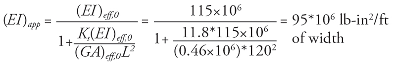 (EI)app is adjusted per NDS Appendix D and Appendix H to determine (EI)app-min. NDS Commentary C10.4.1 provides additional information on this adjustment. Next, the allowable column capacity is calculated.
(EI)app-min = 0.518 (EI)app = 49.0 × 10⁶ lb-in2/ft of width
PcE = π2 (EI)app-min / L2 = 34.0 × 10³ lb/ft of width (NDS C3.7.1.5)
CD = 1.0 (NDS Table 2.3.2)
Pc* = Pc(CD)(CM)(Ct) = 59.4 × 10³ lb/ft of width (NDS C3.7.1.5)
αc = PcE / Pc* = 0.57
c = 0.90
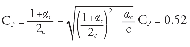 Pc´ = Pc* (CP) = 30.6 × 10³ lb/ft of width
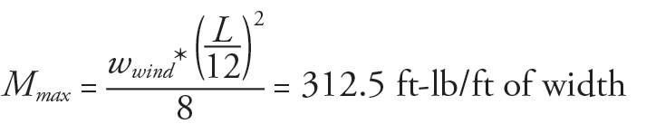
The capacity of 30,600 lbs per foot of wall exceeds the demand of 22,500 lbs per foot of wall. Next, the bending capacity will be checked. For wind loads, the load duration factor (CD) is assumed to equal 1.6. The applied moment due to wind is calculated as:
 The beam stability factor is determined based on the provisions in NDS 3.3.3.1. In this example, d = 4 1⁄8 inches is less than b = 12 inches, so CL = 1.0. The adjusted capacity is then calculated as:
(FbS)eff´ = ((FbS)eff,f,0)(CD)(CM)(CL)(Ct) = 7,240 ft-lb/ft of width
The capacity exceeds the maximum applied moment, so the design is sufficient for bending. Since the member is subject to combined loads, a bending and axial interaction check is required per NDS 3.9.2. For this example, Equation C3.9.2-3 is used.
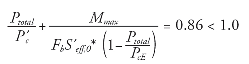
The interaction equation summation is less than 1.0, so the design is sufficient for the combined bending and axial loads specified.
While CLT has been included in the NDS, there currently is no standard design method for in-plane shear of CLT walls. The existing CLT structures in the U.S. have been designed using the alternate methods and materials provisions allowed in the IBC. These designs would have been conducted using the CLT manufacturer’s specifications, and values are typically derived from testing. Currently, not all manufacturers have design values or procedures available. CLT shear wall shear capacities are not in the 2015 Special Design Provisions for Wind and Seismic (SDPWS), but procedures for the design of CLT shear walls and determination of CLT shear wall shear capacities are being balloted for inclusion in the upcoming 2021 SDPWS. In the interim, some designers, in cooperation with the CLT manufacturer, may choose to go through the exercise of determining appropriate shear values for CLT walls. In contrast, others may use a different vertical lateral resisting system that is included in ASCE 7.
Fire Design
For any products that are utilized in buildings, fire is a significant consideration, and wood is inherently fire resistant because of its innate ability to slow down the progression of the fire. There are seven methods in the IBC for establishing fire resistance; one such method, per Section 722, is calculating fire resistance per Chapter 16 of the NDS. This method determines the depth of char required to provide up to 2 hours of fire resistance. For more information, see the Code Updates article in the June 2020 online issue of STRUCTURE.
Future of CLT
Although designers around the world have been constructing taller wood buildings using mass timber (up to 24 stories in height) every year, the current U.S. building codes limit mass timber to 6 stories. However, the tide is changing under the new building codes. In December 2015, in response to requests from building officials, the International Code Council (ICC) Board established the ICC Ad Hoc Committee on Tall Wood Buildings (TWB). The committee was tasked with exploring the science and investigating the feasibility of tall wood buildings, and to take action on developing code changes to the IBC for tall wood buildings. As a result of the thorough research and hard work of this committee, starting with the 2021 IBC, designers will be allowed to design taller mass timber structures up to 18 stories, depending on, among other things, the occupancy, fire protection, egress, and lateral resisting system. Other areas of the world are using mass timber to reach heights of 24 stories. For more in-depth information on the code changes, see https://awc.org/tallmasstimber.■