
How Tall Mass Timber Touches the Sky and Matches the Fire Performance of Traditional Non-Combustible Construction Types
With the adoption of the 2021 International Building Code (IBC), municipalities across the United States will have the ability to build wood buildings taller than ever before. With three new types of construction, Type IV-A, IV-B, and IV-C, mass timber buildings will allow design professionals to erect wood buildings up to 18 stories in height. Figure 1 represents the maximum permitted number of stories under the Type IV-A code change. While these structures are constructed from wood, they are not conventional light-frame construction, and the structural behavior and fire resistance of mass timber structures are not comparable to light-frame construction.
The new provisions for Type IV-A, IV-B, and IV-C construction were developed by the International Code Council’s (ICC) Tall Wood Building (TWB) Ad Hoc Committee. One of the main objectives of the TWB was to develop code provisions that incorporated the inherent fire resistance of mass timber wood structural components into the overall fire-resistance rating (FRR) for the three new construction types. One-third of the required Fire Resistance Rating (FRR) must come from the structural mass of the timber itself, while the other two-thirds must come from noncombustible protection (typically fire-rated Type X gypsum board).
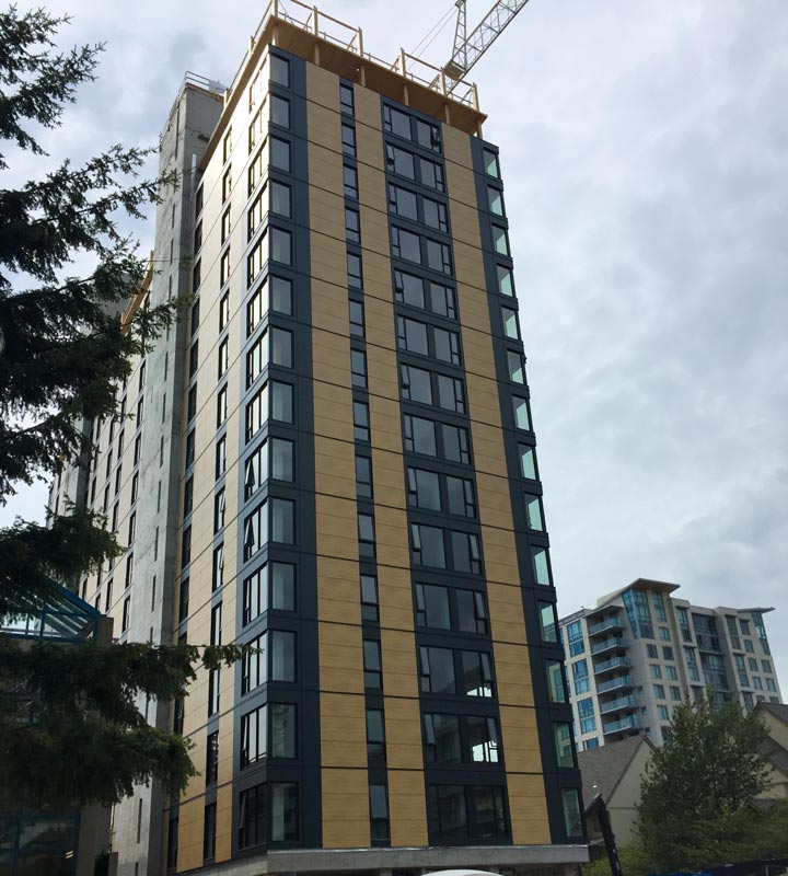
Figure 1. Brock Commons-Student Housing, Vancouver, BC. Currently the tallest mass timber building in North America at 18 stories.
Under the provisions in the 2021 IBC Section 602.4.2.2.2 for noncombustible protection in Type IV-B construction, up to 20% of the ceiling or 40% of the walls are permitted to be exposed wood, based on the floor area in any dwelling unit or fire area. Even though limited amounts of exposed wood surfaces are permitted, each building element must still meet the FRR required for Type IV-B without noncombustible protection. This means the design professional must size the section in question to account for wood charring. The charring rate of wood is non-linear, but the char depth, achar, can be easily quantified using procedures from Chapter 16 of the American Wood Council’s (AWC) 2018 National Design Specification® (NDS®) for Wood Construction, which is referenced in the IBC. Further details about the Chapter 16 provisions of the NDS can be found in AWC’s Technical Report 10 (TR-10): Calculating the Fire Resistance of Wood Members and Assemblies, which is referenced in the NDS Commentary to Chapter 16.
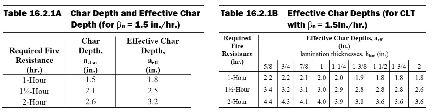
Figure 2. Effective char depth, aeff, from 2018 NDS Chapter 16.
For structural calculations, the effective char depth, aeff, is estimated to be 20% deeper than achar. This accounts for reduced strength and stiffness in the elevated temperature zone in the wood behind the char layer that has not charred yet but has been heated due to the fire. Tables 16.2.1A and 16.2.1B from the NDS (Figure 2) provide aeff values for use in fire resistance calculations of exposed wood members and exposed cross-laminated timber slabs, respectively, for fire exposure durations of up to 2 hours, based on a nominal char rate of 1.5 inches/hr.
While TR10 compiles extensive test data and calculations for wood members and assemblies tested in accordance with ASTM E119 Standard Test Methods for Fire Tests of Building Construction and Materials as required by the IBC. Additional non-standard fire tests were conducted in support of tall mass timber code changes. Photos from full scale, two-story compartment tests conducted at the U.S. Alcohol, Tobacco, Firearms, and Explosives (ATF) Research Laboratory in Beltsville, Maryland, are shown in Figure 3. The photos reveal a char layer and uncharred wood, which was insulated from the fire by the char layer.
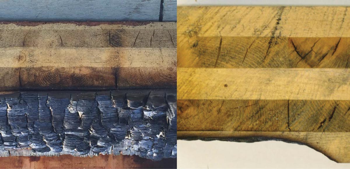
Figure 3. Left, Oblique of 5-ply CLT panel from exposed, ATF Test #3; Right, Cross section showing char removed and remaining laminations.
The IBC addresses equivalent fire risk by regulating features that affect fire performance; taller buildings or combustible construction need more stringent fire protection measures. Unlike noncombustible construction, which has no limitations on height or number of stories (Type I-A), the maximum height and number of stories for the tallest Type IV-A building are limited to 270 feet and eighteen (18) stories. For an 18-story building constructed out of mass timber, a three-hour fire-resistance rating is required for the primary structural frame. As an example, in a Type IV-A Business occupancy building constructed of mass timber, the primary structural frame members will need three (3) layers of 5⁄8 inch, Type X drywall for 120 minutes of fire resistance, plus an additional 60 minutes of fire resistance from the increased section of the mass timber itself. These requirements are especially crucial to the structural engineer or other design professionals because, depending on the structural support system, it may be possible to reduce the FRR of the secondary structural members to two (2) hours.
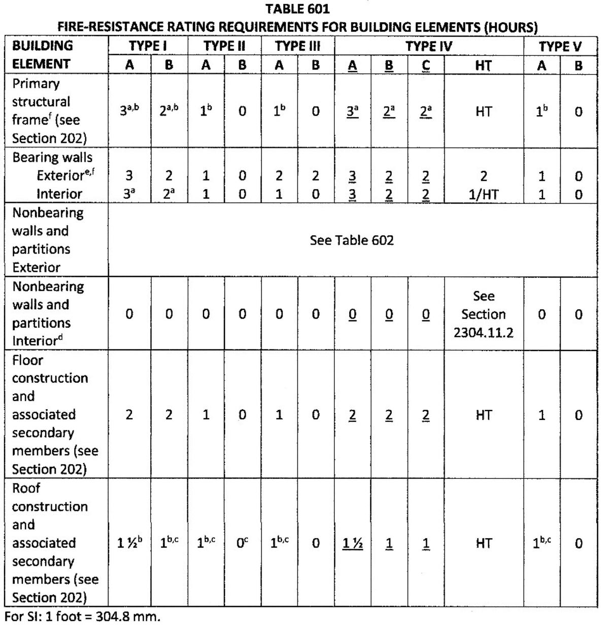
Figure 4. Updated building element fire resistance table per 2021 IBC.
Both of the taller types of mass timber buildings (IV-A and IV-B) mandate the use of a minimum one-inch-thick noncombustible floor topping. In the new 2021 IBC, Table 601 Fire-Resistance Rating Requirements for Building Elements (Figure 4), the various requirements for both the primary structural frame and the floor construction and associated secondary members is evident. The new Tall Mass Timber construction performance requirements more closely resemble the Type I-A and I-B FRR than the traditional Type IV-HT classification, which must only meet the minimum dimensions associated with the construction type.
Fire Design
Compliance with the upcoming 2021 IBC provisions necessitates providing the required FRR for all mass timber elements. In the 2021 IBC, Type IV-C construction will allow fully exposed mass timber elements in buildings up to 85 feet in height, while requiring a 2-hour FRR for the structural frame. The NDS gives provisions for the calculation of fire resistance for exposed wood members, including cross-laminated timber (CLT), in Chapter 16. NDS Table 16.2.1B (Figure 2) provides effective char depths for CLT manufactured in accordance with ANSI/APA PRG 320: Standard for Performance-Rated Cross-Laminated Timber. NDS Chapter 16 is referenced in the IBC as an acceptable method of determining fire resistance and contains many important provisions for doing so. The NDS provisions for fire resistance calculations are only conducted using allowable stress design (ASD), since ASD is the primary method covered in ASTM E119.
Design Example
This example demonstrates calculations for the required section dimensions for a 2-hour structural fire resistance time when subjected to an ASTM E119 fire exposure test. ASTM E119 uses a standard time and temperature curve that is repeatable in the laboratory and is the referenced standard fire exposure for determining fire resistance ratings in the IBC.
A CLT bearing wall with an unbraced height of L = 120 inches loaded in compression in the strong-axis is analyzed.
The design loads are:
Live load = wlive = 14,000 plf
Dead load (including estimated self-weight) = wdead = 6,150 plf
Walls above are supported on a CLT floor slab and aligned with a CLT wall below. Sealing of wall joints with fire-rated caulk restricts hot gases from venting through half-lap joints at the edges of CLT panel sections (another new requirement for mass timber construction).
Compression Design
Wall loads:
Pdead = 6,150 lb/ft of width (dead load)
Plive = 14,000 lb/ft of width (live load)
Ptotal = Pdead + Plive = 20,200 lb/ft of width (total load)
From ANSI/APA PRG 320-18, select a 7-ply CLT panel made from 1 3⁄8-inch x 3½-inch lumber boards (CLT thickness of 9 5⁄8 inches). For CLT grade E1, tabulated properties are taken from ANSI/APA PRG 320-18 Tables A1 and A2.
Fc,0 = 1,800 psi Reference compression stress (PRG 320 Table A1)
FbSeff,0 = 18,375 ft-lb/ft of width Reference bending moment (PRG 320 Table A2)
EIeff,0 = 1,089 x 106 psi/ft of width Reference bending stiffness (PRG 320 Table A2)
GAeff,0 = 1.4 x 10⁶ lb/ft of width Reference shear stiffness, lb/ft of width (PRG 320 Table A2)
L = 120 in. Wall length
Calculate Effective Wall Compression Capacity
Area parallel to grain for a 7-ply panel is based on 4 plies @ 1 3/8-inch-thick, per foot of panel width (NDS 10.3.1).
Aparallel = 4 * 1.375 * 12 = 66 in2/ft of width
Pc = Fc0 ⋅Aparallel = 118,800 lb/ft of widt Effective Wall Compression Capacity (NDS 10.3.1)
Calculate Apparent Wall Bending Stiffness
Using NDS Eqn. 10.4-1, the apparent bending stiffness can be calculated. Assume pinned-pinned end fixity.
Ks = 11.8 Shear deformation adjustment factor (NDS Table 10.4.1.1)
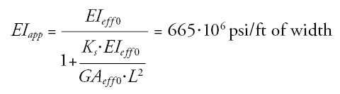
EIapp is adjusted per NDS Appendix D and Appendix H to determine EIapp-min (NDS C10.4.1)
EIapp-min = 0.5184 EIapp = 345 x 106 psi/ft of width
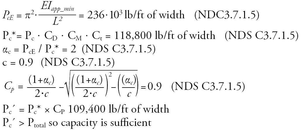
Calculate Adjusted Allowable Wall Capacity
Assume all NDS adjustment factors equal 1.0 (CD = Ct = CM = 1.0).
Fire Design
Mass loss due to charring will be neglected, so loading is unchanged. Calculating char depth per NDS Table 16.2.1B gives an aeff = 3.8 in.
For this example, char penetrates the first three laminations, including the first two strong axis laminations. The contribution of the uncharred crossing layer to buckling resistance is minimal, so it will be neglected. The post-char wall can be designed as an eccentrically loaded 3-ply CLT column.
3-ply panel properties for CLT grade E1 panel are in ANSI/APA PRG 320-18 Annex A.
Fc,0 = 1,800 psi Reference compression stress (PRG 320 Table A1)
FbSeff,0 = 4,525 ft-lb/ft of width Reference bending moment (PRG 320 Table A2)
EIeff,0 = 115 x 106 psi/ft of width Reference bending stiffness (PRG 320 Table A2)
GAeff,0 = 0.46 x 10⁶ lb/ft of widt Reference shear stiffness, lb/ft of width (PRG 320 Table A2)
Area parallel to grain is equal to breadth (b) x depth (d) of the remaining two strong axis plies.
Aparallel = 2 * 12 * 1.375 = 33 in2/ft of width (NDS 10.3.1)
Pc = Fc0 ⋅ Aparallel = 59,400 lb/ft of width (NDS 10.3.1)
Calculate Apparent Wall Bending Stiffness
Using NDS Eqn. 10.4-1, the apparent bending stiffness can be calculated. Assume pinned-pinned end fixity.
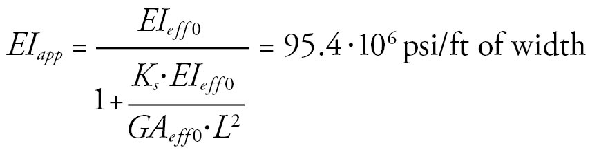
The method of adjustment of EIapp per NDS Appendix D and Appendix H to determine EIapp-min is unchanged.
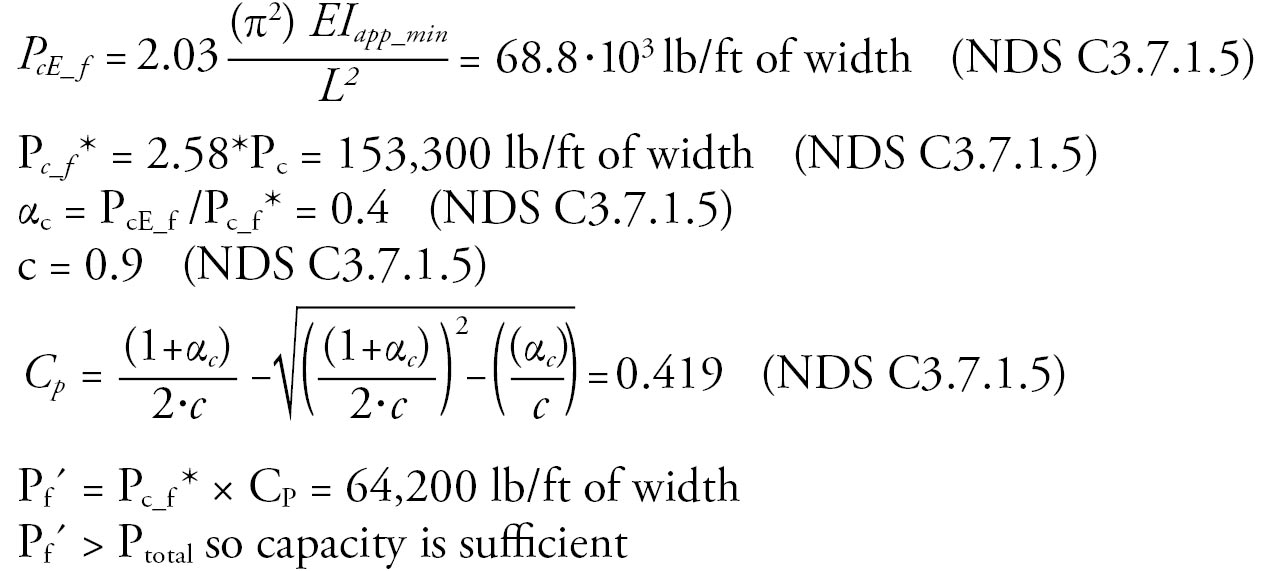
EIapp-min = 0.5184 EIapp = 49.5 × 10⁶ psi/ft of width
Using the general form of the Euler buckling equation, with the “f” subscript denoting fire design. (NDS C3.7.1.5):
Initially, the wall is assumed to be loaded concentrically; however, as one side of the wall chars,the load becomes eccentric. The eccentricity in this example is half the difference in depth between a 7-ply CLT member and a 3-ply member.
e = (9.625 – 4.125) / 2 = 2.75
Calculate Resisting Moment
Assume all applicable NDS adjustment factors = 1.0
CL = 1.0
M´f = 2.85 . FbSeff0.CL = 12,900 ft-lb/ft of width = 154,755 in-lb/ft of width (NDS 16.2.2)
Using the general form of NDS Eqn. 15.4-3 for wood columns:
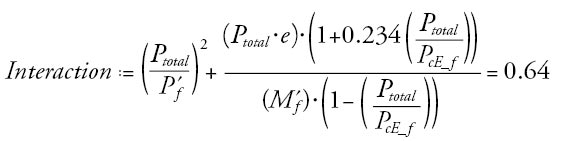
The interaction equation is less than 1.0, so the design is sufficient.
Conclusion
In summary, the changes to the IBC will permit mid- to high-rise buildings to be constructed for all occupancy types, provided that the stringent fire-resistant construction details and active and passive fire protection are installed following the 2021 IBC. The addition of the new construction Types IV-A, IV-B, and IV-C will provide designers with the flexibility to use new materials to engineer buildings that are safe, efficient, and sustainable.
For additional information on Tall Mass Timber and the Tall Wood Building Ad Hoc Committee, as well as additional information on the rigorous fire testing performed at the ATF, please refer to www.awc.org/tallmasstimber.■