Rock is hard. While the degree of hardness varies, it is objectively harder than soil. Geotechnical foundation design has largely concentrated on the analysis of soil. In-situ site investigation techniques and constitutive modeling efforts are devoted to characterization and performance prediction of non-linear soil behavior. When it comes to rock, the default assumption has been that rock is unyielding, and the design of a foundation supported on it should be based on the material parameters of the structural element.
Such is the case for driven steel piles. Pound a piece of steel into the ground to the point it stops on apparent rock, and most everyone agrees that the pile will fully develop its structural capacity. However, until relatively recently, building codes did not provide similar consideration for drilled shafts. The rock had to be proven to be capable of supporting the applied point load. Pointing out the numerical fallacy of the argument – that the tip stress of a driven steel pile in service is 7 to 10 times higher than a cast-in-place concrete drilled shaft – invariably resulted in disapproving stares from building officials.
Not to disparage building officials, this point is intended to exemplify the discomfort many in the industry have in intuitively reconciling the axial capacity of foundations. For the compact sections used in piling, the structural capacity is readily determined as the tip area of steel times the allowable material stress. Under the maximum stress limit of the International Building Code (IBC), the commonly used HP 12×53 section has a capacity of about 387 kips. For comparison, an uncased, 4-foot-diameter drilled shaft constructed with 6,000 psi concrete has an axial capacity of slightly more than 3,250 kips – an 8-fold comparative increase on a single element. Change the diameter to 7 feet, and the capacity approaches 10,000 kips. From the viewpoint of the rock, the driven pile is a more significant concern. Neither foundation realistically threatens it with failure, but the tip stress of the pile could locally crush the rock and penetrate the surface. The concentration of the stress over the small pile footprint also increases the localized influence-variations in the rock (e,g., fractures, clay-filled seams, voids) may have on the performance of the element. Despite the higher likelihood of punching failure with piling, designers tend to fixate on the much larger capacity number and determine that the magnitude of the load justifies greater scrutiny and caution in the design of drilled shafts.
For 110 North Wacker Drive in Chicago, the provided core foundations would support nearly 40,000 kips. The design equivalent end bearing of the rock-socketed drilled shafts was 600 ksf, which is 50% greater than the maximum allowable presumptive bearing capacity in the Chicago Building Code (CBC).
When completed in 2020 after approximately 2½ years of construction, the 56-story tower will have an architectural height of 817 feet. The gross footprint area will encompass slightly less than 1.8M square feet over an occupied height of 752 feet. In a reflection of changing commuter habits, only 110 parking spaces are provided over 2 lower levels.
After a long history of service as a commercial waterway and an industrial transport corridor, the Chicago River, which defines two sides of the Loop, is experiencing a renaissance of redevelopment. As recently as the 1990s, buildings were deliberately designed with a rear-facing to the river to avoid interaction with what was often a caustic and foul-smelling soup of shipping traffic, pollutants, and stormwater runoff, swirled with occasional untreated discharges from upstream manufacturing. Today, the Chicago River is being embraced as an asset for real estate, commercialization, and tourism. The City of Chicago requires new construction on the North and South Branches to provide open public access to the riverfront. Rather than set back the entire structure, 110 North Wacker was designed with a multi-story, open-air overhang, which provides the requisite public space while still maximizing the building footprint on the trapezoidal site. An inspired sawtooth floorplate, which can accommodate as many as nine corner offices on the riverside, enables the tower to feature a dual-front facing. Architecturally, both the street and the riverside are front doors to the building. The perimeter structure loading is transferred through the overhang by three trident columns.
For its height, 110 North Wacker is a comparatively heavy building. Had it been designed 15 or 20 years ago, it likely would have been a light steel frame building as the majority of the older 50- to 60-story high-rises are in Chicago. While code changes and advancements in analytic methods that allow for consideration of an ever-growing list of load combinations can be blamed for some of the increase in building weight, it is the greater use of concrete in the structure and the changes in design approach to provide occupant usage-driven spaces which have had the greatest impact on the foundation demand.
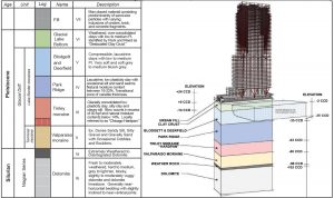
The Chicago subsoils are predominantly composed of large masses of clay and silt derived from the Devonian shale, which occupied the Lake Michigan basin. The clays were deposited as a series of ground moraines (or till sheets) lying one atop another by the advances and retreats of the continental ice sheet during the Wisconsin glacial period. Geologically, six separate till sheets, representing six advances and retreats of the ice front, have been identified: (from bottom up, typically) the Valparaiso moraine, Tinley moraine, and the Lake Border moraine which is comprised of the Park Ridge, Deerfield, Blodgett, and Highland Park till sheets. Within the project site footprint, the soil profile is about 120 feet thick. It includes 20 feet of urban fill and 40 to 50 feet of compressible and lacustrine clay. The hard, silty clay and clayey silt of the Tinley Moraine till sheet, which is locally referred to as “hardpan,” is located about 80 feet below the street grade of Upper Wacker Drive. The majority of the 1,300+ high-rises which form the Chicago skyline are supported on belled caisson foundations bearing in this layer. The introduction of in-situ pressuremeter testing increased the allowable bearing capacity in the hardpan from 15 ksf in the 1960s to more than 50 ksf today.
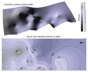
A 20- to a 25-foot-thick layer of silt, sandy silt, and gravel is present below the hardpan, immediately above the bedrock. The Chicago bedrock consists of shallow dolomite formations mainly of Silurian age and deep sandstone and dolomite formations of Cambrian and Ordovician age. The Niagaran series immediately underlies the glacial drift, and it varies in thickness from 240 to 425 feet, generally increasing eastwards towards the Lake Michigan basin. The rock surface in the majority of the Chicago Loop is relatively flat. The relief over the 400-foot site length (north to south) is only 4 to 6 feet.
For permitting, the City of Chicago required each of the 37 socketed drilled shaft foundations to be precored to evaluate the rock. The presumptive bearing capacity provided in the CBC requires that the rock be “solid” to a depth of at least 8 feet below the tip of the rock socket. In the early days of hand-dug shafts, an acceptably solid rock was determined by driving a steel pick into the base material and evaluating the tone of the ring of the strike. This may have contributed to the code language meant to clarify the concept of solid rock further by defining it as sound, unweathered limestone without visible voids.
Setting aside the quibble that the underlying bedrock in Chicago is dolomite rather than limestone, it is essential to note that the building code relies only on qualitative assessment of the rock; it does not include requirements for determination of mechanical properties. Although the presumptive bearing capacity is limited to 400 ksf for end bearing caissons socketed into rock, this is not an intrinsic property of the rock
The Geological Strength Index (GSI) was introduced by Evert Hoek and Paul Marinos in 2007 as a characterization system to combine geologic assessment of a rock mass with the results of sampling and lab testing to improve analytic performance prediction of tunnels, slopes, and foundations. Before GSI, engineering parameters for rock were largely qualitative assessments of the degree of intactness or integrity of the parent material. While the compressive strength of the rock could, with proper sampling, be readily measured in the laboratory, there was little consideration given to how the structure of the geology would affect the engineering performance in the field.
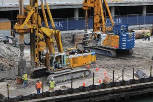
Foundation drilling. Belling tool (undeployed) on a rig in foreground and soil auger mounted on rig at back. Core barrel behind group of onlookers at right rear of frame.
Unconfined compressive strength tests were performed on over 100 samples, and a geotechnical strength index was determined for the rock mass based on visual examination of the recovered cores. The rock exhibited a strength distribution consistent with that for other sites sampled in Chicago. Stress relaxation from drilling and sampling can allow microfractures to open in the recovered cores, and minor irregularities in the end flatness of the samples can cause premature breaks, all of which contribute to the large spread of the data. For the upper 10 to 20 feet of the rock, in which any foundations would be supported, a conservative value of the unconfined compressive strength was determined as 10,000 psi. Utilizing the Rock Mass Rating system, the dolomite classified as “Good to Very Good” rock and the GSI was determined to be between 55 and 65.
The analysis of the rock socket followed the methodology of Carter and Kulhawy, a modified form of which is provided in the AASHTO Standard Specifications for Highway Bridges. The GSI is incorporated into a material strength constant and an exponential coefficient, and the ultimate end bearing is determined from a power function. The side resistance is determined from the square root of the unconfined compressive strength (normalized by atmospheric pressure) multiplied by a scalar coefficient, which considers roughness of the socket sidewalls. The axial capacity of the socket is effectively determined using only two parameters.
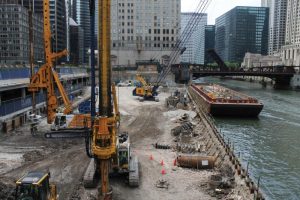
Site looking south. Upper and Lower Wacker Drive to the east (left). The barge moored to the Chicago River Wall provided laydown areas for material storage and a platform to tie reinforcing cages.
For the dolomite recovered from the precores, the ultimate end bearing was predicted to be 1,200 ksf, and the side resistance was determined as 80 ksf. The allowable equivalent end bearing was estimated to be more than 715 ksf for a 6-foot-long rock socket using a factor of safety of 2. Under the presumptive bearing capacity of the CBC, a 6-foot rock socket has an allowable bearing capacity of 400 ksf.
An Osterberg load test was performed to verify capacity and to provide an index for validation of performance prediction. A 34-inch-diameter load cell (the largest available) was installed near the base of a 7-foot-diameter production caisson, and a biaxial load was applied to evaluate socket end bearing and side friction in accordance with ASTM D1143 Standard Test Methods for Deep Foundations Under Static Axial Compressive Load (Method A). At its maximum capacity, the O-Cell applied a sustained bi-directional load of 9,054 kips on a 36-inch-diameter bearing plate, which produced a combined displacement of approximately 1 inch (0.3 inches upward and 0.7 inches downward). The mobilized side resistance was slightly less than 60 ksf, and the end bearing was approximately 900 ksf.
It is worth noting that the load test was taken to the maximum capacity of the O-Cell without initiation of creep or slip along the rock socket sidewall. The test demonstrated more than 1.5 times the design effective end bearing of the drilled shaft, also with no indication of creep or crushing below the socket tip. Assuming the rock was completely decomposed to a cohesionless soil, the end bearing would be expected to be fully mobilized at a deflection of 4 to 5% of the base diameter. A movement between approximately 3 and 3.5 inches could only be achieved in the rock by punching failure. Due to the thickness of the underlying massive rock, material crushing of the shaft concrete would occur before the end bearing could be mobilized. Osterberg load tests at other sites in Chicago have demonstrated similar results.
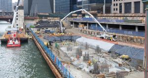
Site looking north. Mud-slab placement in advance of mat slab pour (3,300 cubic yards placed in less than 8 hours) for the building core. Reinforcement projections include interior “bar cassettes” and exterior circular bars.
By any measure, it should be clear that the axial capacity of rock socketed drilled shafts is under-utilized. While it may be possible to mobilize greater side resistance and even create slip using an O-cell in a smaller diameter socket, end bearing failure is unlikely ever to be demonstrated by load testing.
The static analysis using conservative parameters indicates that the material properties of the concrete control the capacity of the drilled shaft – just as it would be for a driven pile.
For the near future, the 56-stories of 110 North Wacker will continue to hold the title of the highest bearing capacity ever permitted in Chicago at 600 ksf. The next step in foundation performance (say 700 or 800 ksf) will have to wait until someone starts producing 14,000 psi concrete, and there is a practical need for a drilled shaft that can support 56,000 kips. Until then, the rock will be waiting.■


