
Those familiar with masonry design understand its benefits for building construction: no other material provides the beauty, strength, durability, design versatility, and sustainable attributes as materials like brick, block, and stone. Unfortunately, however, younger designers or those new to masonry may be reluctant to consider it due to its perceived complexity, the overwhelming options of materials and subassemblies, and the lack of a recognized standard for organizing masonry systems, assemblies, and components. The International Masonry Institute (IMI) is addressing these obstacles by developing a systematic process for designing masonry walls: complimentary access, digital Wall Builder Tool to facilitate the process, and a crowdsourced Masonry Wall Systems Library (imiweb.org/wbt) that applies a logical taxonomy. This design approach quickly and systematically goes through a series of micro-decisions on a small number (eight or fewer) of subassemblies of the wall, resulting in a well-informed system design.
The Paradox of Choice
The Paradox of Choice is a premise put forth by author Barry Schwartz in his 2004 book of the same title that states, “the more choices we are presented with, the more difficult it is to make an informed decision.” The argument posits that even if the options are of good quality and if the consumer or user desires many options to make an educated decision, too many choices will result in a state of paralysis and very likely lead to no decision at all. We encounter decision paralysis in a variety of everyday situations, from choosing a restaurant to dine at, a movie to watch, or what to do on a Friday evening. For design professionals making decisions about materials, structure, and components of a wall, navigating countless options can present the same difficulty.
Consider your experience dining at a Mexican restaurant, where you are presented an extensive menu offering a comprehensive selection of platters, small plates, specials, combos, and a la carte items. Deciding what to order with so many options often feels daunting. At a cafeteria-style restaurant, which limits its menu to five basic items, and prompts you to make a series of micro-decisions about the ingredients you want in your entrée, ordering dinner is much simpler.
Similarly, the Wall Builder Tool simplifies the process of designing a masonry wall system by guiding the user through a logical sequence of components that make up a wall.
Components, Assemblies, and Systems
Because it comprises so many parts and pieces, a masonry wall system can be complex and even intimidating, but a little reverse engineering will make it easier to understand. The key is a three-tiered approach to every masonry wall system. From the granular to the general, there are components, sub-assemblies, and finally, the system itself. If masonry components, also known as masonry materials (for example, a brick, an air barrier, or a wall tie), are the building blocks of masonry sub-assemblies, then masonry sub-assemblies are the building blocks of a masonry wall system. Now that we’ve introduced the hierarchy, for the sake of simplicity, we will refer to a sub-assembly simply as an assembly.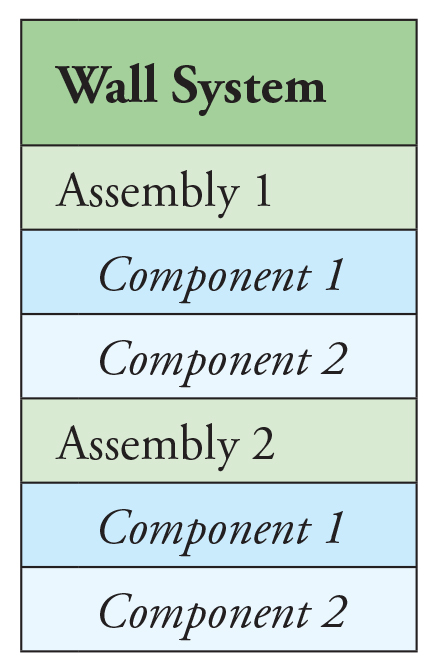
Masonry Wall Assemblies
The key to simplifying masonry walls is the delineation of a manageable number of assemblies. The makeup of any masonry wall system using this approach, no matter how complex, comprises no more than eight subassemblies. A masonry wall may have fewer than eight, but never more than eight assemblies. Not considering the Interior Finish assembly, which is generally out of the engineer’s scope, the primary seven assemblies are identified as follows, listed by location from the inside of the wall working toward the outside:
- Structure
- Sheathing*
- Air/Moisture Barrier*
- Insulation*
- Drainage*
- Attachment*
- Cladding*
* indicates optional assembly
Structure
Structure is the single assembly that every masonry wall requires. In this context, structure refers to the structure of the wall itself, not the framing system of the building, although they may be one in the same as in the case of loadbearing masonry. Examples of wall structure include concrete masonry (reinforced or unreinforced), steel studs, wood studs, or architectural precast concrete panels. In the case of a single wythe CMU wall with no exterior cladding and no interior finish, the Structure assembly would be the only assembly of the wall system; fields B through G would be blank.
Sheathing
If the wall’s structure is loadbearing or light gauge steel or wood studs, it would likely require a sheathing over the studs. The sheathing imparts in-plane rigidity and provides a surface for an air/moisture barrier if desired. For adhered veneers, the sheathing also provides a surface to affix the adhered veneer cladding. Walls with a solid structure like CMU, structural clay masonry, precast, or cast-in-place concrete would likely not make use of the Sheathing assembly.
Air/Moisture Barrier
Although its form and location in the wall may vary, the typical location of an air/moisture barrier is directly over the structure or the sheathing. This assembly may take the form of a sheet or fluid-applied treatment. If the sheathing or the structure already meets requirements for resistance to air leakage outlined in the energy code or other applicable codes, a separate air/moisture barrier may not be required; therefore, this is an optional assembly.
Insulation
With the trend toward sustainable practices and lower energy costs, the thermal performance of walls is more important than ever. Therefore, many walls are designed with insulation that supplements masonry’s natural thermal mass in the wall’s ability to manage thermal changes. Insulation comes in varying types, thicknesses, and locations, and is an important assembly of most masonry walls.
Drainage
Drainage walls, cavity walls, or moisture managed walls are walls with some drainage mechanism to collect and divert moisture that infiltrates the exterior cladding and works its way into the wall. Examples of drainage mechanisms can be as simple as an air space behind the cladding, to more substantial accessories like drainage mats.
Attachment
Walls with a cladding assembly over the wall structure, whether the cladding is anchored or adhered, require a method to attach or affix the cladding to the backing. In the case of anchored veneer, the methods of attachment generally take the form of veneer anchors or wall ties; rainscreen systems typically have a more elaborate framing system that ties the cladding to the structural backing. Adhered veneers may utilize various forms of bonding mortar, either reinforced with lath or unreinforced.
Cladding
Unless the wall is a single wythe masonry wall, it will have a cladding assembly. The cladding, whether full-depth anchored masonry veneer or a thin adhered material, is the exterior skin of the wall. The variety of masonry cladding material, e.g., brick, stone, tile, terra cotta, architectural block, etc., provides the exterior element of beauty in a masonry wall.
Interior Finish
Interior finish is included in the eight subassemblies because it can be an important part of the wall’s design even if not addressed by the engineer.
Design Decisions Sequence
Knowing each of the eight assemblies, the analogy of the build-your-own burrito experience provides a similar hierarchy and progression to the decision-making process. The first two decisions in the burrito line are the most important, and they are the ones that will inform the subsequent decisions: the type of protein and the type of wrap. In designing a wall system, the first decisions are how the wall supports itself and what it will look like. Subsequent options follow, like the insulation (or not), the drainage device (or lack thereof), and the interior finish.
Once the wall structure and cladding are selected, the Wall Builder Tool is intelligent when it comes to subsequent options. For example, if no cladding is selected, the program knows it to be a single wythe wall and will only offer the choice of “none” for the fields of sheathing, attachment, and drainage. If the structure is concrete masonry or any assembly other than wood studs, then corrugated wall ties will not be offered as an option. TMS 402, Building Code Requirements for Masonry Structures, does not allow those types of ties with those types of backings. If a thin material is selected as cladding, the only methods of attachment offered are the direct bond materials rather than mechanical anchors.
Deliverables
Once the user has completed the systematic process of selecting each of the subassemblies based on project requirements, he or she can download a PDF graphic of the wall system. This graphic shows each of the eight or fewer assemblies in a three-dimensional exploded view presented as in the field of the wall. A descriptive sheet title is automatically generated as well as a unique wall number, both appearing on the drawing sheet. Each time a wall is built online, the program pushes that same PDF file to IMI, who curates the user-generated Wall Systems Library.
The PDF graphic depicts only the field of the wall and not any special conditions like penetrations, terminations, or accommodations for movement or moisture. The Wall Builder Tool is intended to be a design aid in the conceptual or schematic stages of design. It does not generate complex construction details or a specification (IMI has other resources for those), but it does inform the details and the specifications since the generated walls provide a perfect starting point for the design development phase.
The PDF graphic can also serve as a communication tool among the design disciplines and even the client. It is also a useful teaching tool for engineering or architecture students or practicing professionals who are just becoming conversant with masonry design.
BIM Ready
Currently, the output is limited to the PDF graphic. However, BIM users can extrapolate the information into a file compatible with their BIM platform of choice. The next phase of the Wall Builder Tool may introduce Dynamo scripts able to generate Revit files of the wall designed, so it can immediately be brought into the BIM model.
Standardization
The Wall Builder Tool and the Wall Systems Library are the masonry industry’s first step at developing a universally recognized taxonomy for masonry walls. The large number of combinations of materials in a masonry wall results in hundreds of thousands of unique walls, making it difficult to attempt any method of standardization until now. Because computer logic assigns a wall number based on the materials selected in each assembly and is adept at capturing and cataloging every wall designed using the Wall Builder Tool, the masonry industry is one step closer to achieving a standard classification system for masonry walls.■